5-6
Chapter
5
USER WIRING AND USER PIPIN
1-3 Cable carrier specifications
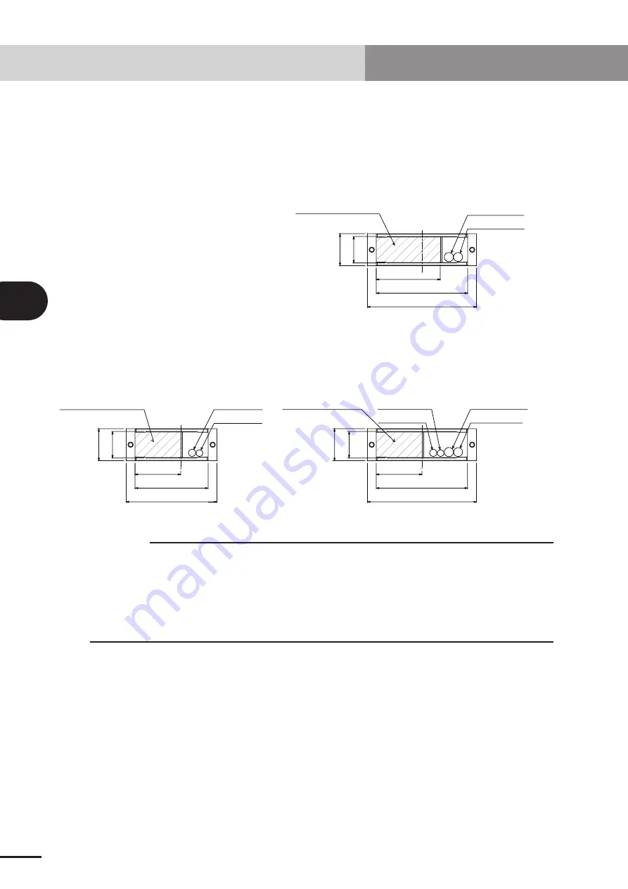
The cross-sectional shape of the cable carrier, and the shape of the cable mounted
initially by YAMAHA are shown below.
3-axis specifications X-Y cable carrier
Y-Z cable carrier
2-axis specifications X-Y cable carrier
29
35
29
35
50
80
100
Power wire
F
7.6
Signal wire
F
8.2
50
100
120
Signal wire
F
10.1
Power wire
F
7.6
Signal wire
F
8.2
Power wire
F
9.8
User wiring area
User wiring area
29
35
120
100
70
Power wire
F
9.8
Signal wire
F
10.1
User wiring area
c
CAUTION
• Harness and air tube must be laid in the unoccupied area. Do not set the user
wiring/piping in the YAMAHA robot cable domain.
• When setting the harness and air tube into the cable carrier, make sure that the
total cross-sectional area of all wires and pipes, including the YAMAHA cable,
inside the cable carrier does not exceed 30% of the cable carrier’s cross-
sectional
area.
1. Cable carrier type
Summary of Contents for NXY
Page 2: ......
Page 6: ......
Page 22: ......
Page 26: ...2 4 MEMO ...
Page 28: ......
Page 32: ...3 4 MEMO ...
Page 34: ......
Page 38: ...4 4 MEMO ...
Page 40: ......
Page 48: ......

