P-250
11
9.
Headphones Jack Assembly, HP Circuit Board
(Time required: about 10 minutes)
9-1
Open the control panel unit. (See procedure 1.)
9-2
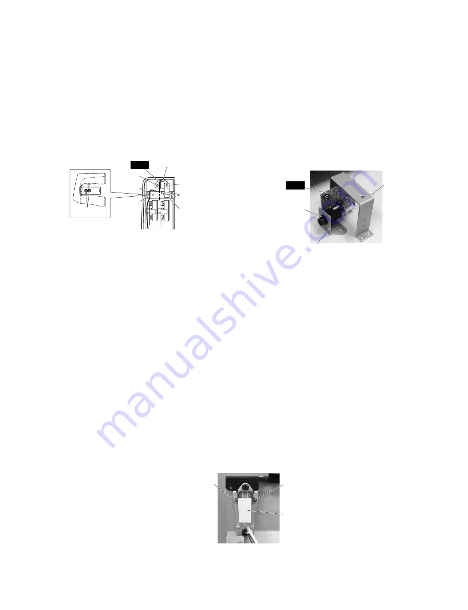
Remove the two (2) screws marked [250F], the four (4)
screws marked [750A], the screw marked [730C] and the
screw marked [310]. The headphones jack assembly and
the side cover holder L can then be removed. (Fig. 12)
9-3
Remove the hexagonal nut marked [660b]. The HP circuit
board can then be removed from the headphones jack holder.
(Fig. 13)
Side cover holder L
(取付金具
L
)
Headphones jack holder
(
H.P.
取付金具)
[660b]
Fig. 12
(図
12
)
• Headphones jack assembly
(
H.P. Ass'y
)
[750A]
Side cover holder L
(取付金具
L
)
Headphones jack assembly
(
H.P. Ass'y
)
[750A]
[750A]
[730C]
[250F]
[310]
HP
[310]: PW Head Tapping Screw-B 3.0 x 10⁻⁸ MFZN2Y (WB085800)
[730C]: Bind Head Tapping Screw-B 3.0 x 8 MFZN2Y (EP600250)
[750A]: Bind Head Tapping Screw-B 4.0 x 12 MFZN2BL (VR138400)
+
PWH_B
タイト
+バインド
B
タイト
+バインド
B
タイト
Fig. 13
(図
13
)
[660b]: Hexagonal Nut 12.0 14 x 2 MFZN2BL (VB508600)
特殊六角ナット
HP
10.
Control Panel Unit, Side Cover L (or R)
(Time required: about 10 minutes)
10-1
Open the control panel unit. (See procedure 1.)
10-2
Remove the four (4) screws marked [170D] and the two
(2) screws marked [220B]. The control panel unit with side
covers can then be removed from the keybed. (Fig. 3)
10-3
Remove the four (4) screws marked [740] and the two (2)
screws marked [750B]. The side cover L or R can then be
removed. (Fig. 3)
*
The left and right side cover each can then be removed in
the same manner.
11.
Power Switch
(Time required: about 10 minutes)
11-1
Open the control panel unit. (See procedure 1.)
11-2
Remove the side cover L. (See procedure 10.)
11-3
Remove the two (2) screws marked [610d]. The power
switch (push switch) can then be removed. (Fig. 14)
Push Switch
(プッシュスイッチ)
[610d]
[610d]
Fig. 14
(図
14
)
[610d]: Bind Head Tapping Screw-C 3.0 x 6 MFZN2Y (EP630390)
+バインド
C
タイト
9.
H.P.Ass'y、HP シート
(所要時間:約 10 分)
9-1
CP ユニットを開けます。
(1 項 参照)
9-2
[250F]のネジ 2 本、[750A]のネジ 4 本、[730C]のネジ 1
本、
[310]のネジ 1 本を外し、取付金具 L と H.P.Ass'y を
外します。
(図 12)
9-3
[660b]の特殊六角ナット 1 個を外し、H.P. 取付金具か
ら HP シートを外します。
(図 13)
10.
CP ユニット、腕木 L・R
(所要時間:約 10 分)
10-1
CP ユニットを開けます。
(1 項 参照)
10-2
[170D]のネジ 4 本、[220B]のネジ 2 本を外し、棚板か
ら CP ユニット(腕木と一緒に)を外します。(図 3)
10-3
[740]のネジ 4 本、
[750B]のネジ 2 本を外し、腕木 L ま
たは R を外します。
(図 3)
※
左右の腕木は、それぞれ同じ方法で外すことができ
ます。
11.
電源スイッチ
(所要時間:約 10 分)
11-1
CP ユニットを開けます。
(1 項 参照)
11-2
腕木 L を外します。
(10 項 参照)
11-3
[610d]のネジ 2 本を外し、電源スイッチ(プッシュ
SW)を外します。(図 14)


