P-250
13
14-1
GHD EBUS L, MK SUB Circuit Board
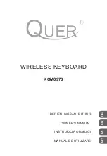
Remove the seven (7) screws marked [260A]. The GHD
EBUS L and MK SUB circuit boards can then be removed.
(Fig. 18 and photo 1)
14-2
GHD M Circuit Board
Remove the five (5) screws marked [260B] and the screw
marked [262]. The GHD M circuit board can then be re-
moved. (Fig. 18)
14-3
GHD H Circuit Board
Remove the four (4) screws marked [260C] and the screw
marked [262]. The GHD H circuit board can then be re-
moved. (Fig. 18)
*
Keys can be removed without removing the circuit boards.
*
After removing the GHD EBUS L, GHD M and GHD H
circuit boards, and the rubbers can then be removed.
14.
Disassembling the Keyboard
*
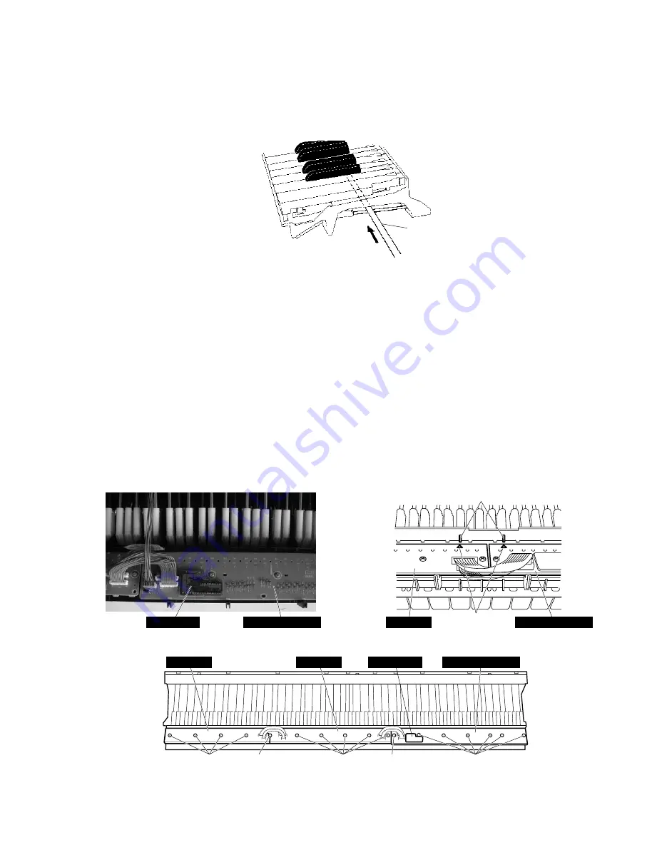
After inserting a round stick (Rod: TX000670) between the
frame and the keys, remove the circuit boards. (Fig. 17)
Round stick
(Rod: TX000670)
(丸棒)
Fig. 17
(図
17
)
Fig. 18
(図
18
)
Fig. 18-1
(図
18-1
)
Photo 1
(写真
1
)
[260]: Bind Head Tapping Screw-P 3.0 x 10 MFZN2 (VT413400)
+バインド
P
タイト
[262]: PW Head Tapping Screw-P 3.0 x 10⁻¹⁰ MFC2BL (V8833200)
+
PWHP
タイト
MK SUB
MK SUB
GHD EBUS L
[260C]
[260B]
[262]
[260A]
[260A]
Hook
(フック)
Triangle mark
(三角マーク)
GHD EBUS L
GHD EBUS L
GHD M
GHD M
GHD H
14-1
GHD EBUS L, MK SUB シート
[260A]のネジ7本を外し、GHD EBUS L, MK SUBシー
トを外します。
(図 18、写真 1)
14-2
GHD M シート
[260B]のネジ 5 本と[262]のネジ 1 本を外し、GHD M
シートを外します。
(図 18)
14-3
GHD H シート
[260C]のネジ 4 本と[262]のネジ 1 本を外し、GHD H
シートを外します。
(図 18)
※
白鍵と黒鍵は、GHD EBUS Lシート、GHD Mシート、
GHD Hシートを外さなくても、外すことができます。
14.
GHD EBUS 鍵盤の分解
※
シートをはずす前に、接点ゴムを歪ませないように、
フレームとハンマーの間に丸棒(ロッド:TX000670)
を挿入しておきます。
(図 17)


