P-250
7
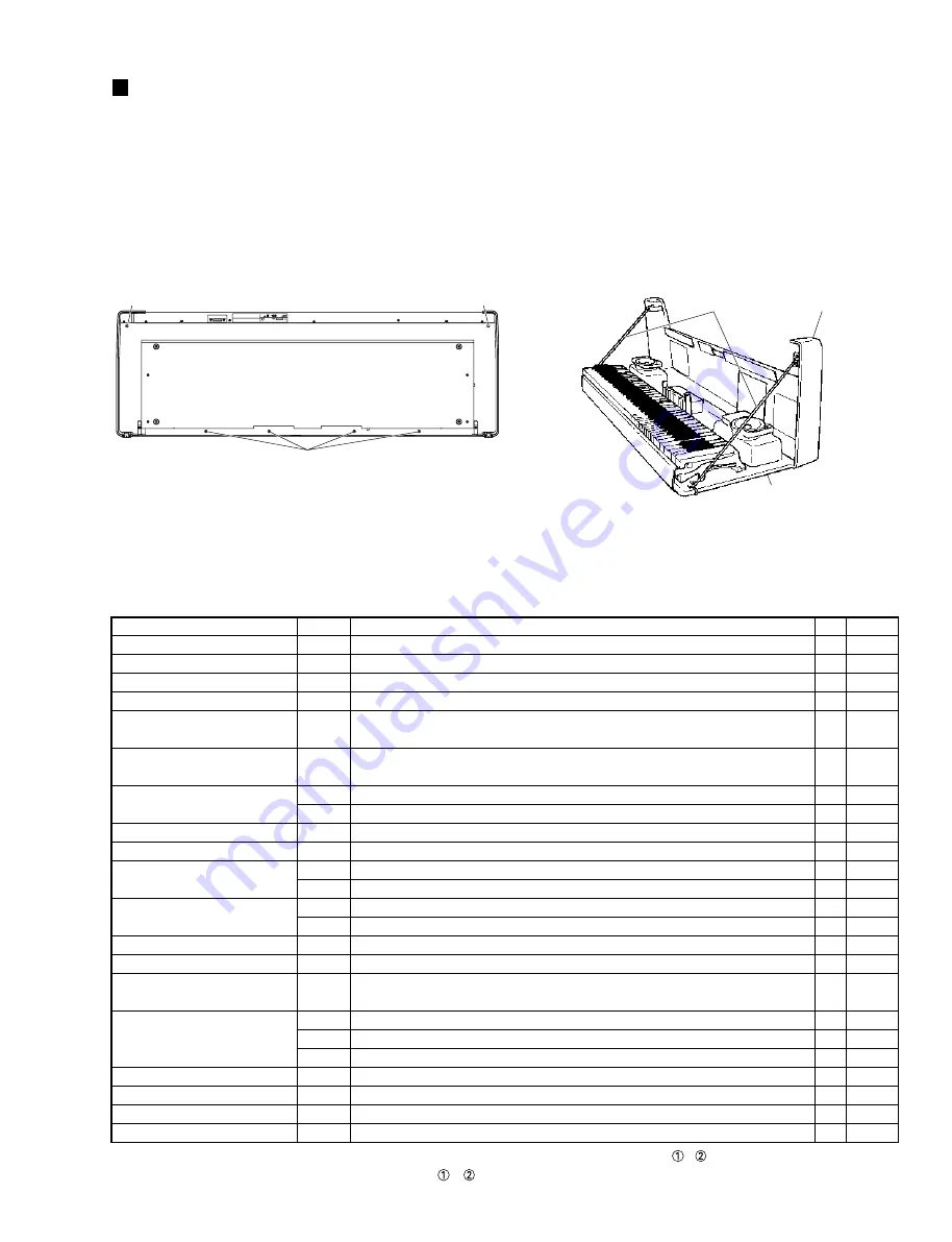
Fig. 1
(図
1
)
Fig. 2
(図
2
)
[240]: Pan Head Screw PW 5.0 x 25 MFZN2BL (VB919400)
+ナベ尖り先小ネジ
<Bottom side>
(底面)
[240]
[240]
[240]
Control panel unit
(
CP
ユニット)
Keybed
(棚板)
Strings
(紐)
DISASSEMBLY PROCEDURE
1.
Opening Control Panel Unit
(Time required: about 3 minutes)
1-1
Remove the six (6) screws marked [240] located under the
keybed. (Fig. 1)
*
Lift the control panel unit from the front and pass strings
through two side plates and both ends of the keybed, as
shown in the figure so that hinges are not damaged. (Fig. 2)
2.
Circuit Boards and Assemblies
(Time required: about 4–7 minutes)
Remove the following screws after opening the control panel
unit. Each circuit board and assembly can then be removed.
Circuit Board and Unit
A-JACK Assembly
D-JACK Assembly
FU Cover (U model only)
FU60 Assembly
Wheel Assembly (PITCH)
(ホイール
Ass’y
)
Wheel Assembly (MODULATION)
(ホイール
Ass’y
)
MV2
LCD
(液晶ディスプレイ)
PNR *
PNL *
PN-EQ *
MA Cover (U model only)
MA60 Assembly
Power Transformer (J, E, B, A, K models)
(電源トランス)
Power Transformer (U model)
(電源トランス)
Speaker Box Assembly L
Speaker Box Assembly R
Speaker Grille Assembly L
Speaker Grille Assembly R
Ref. No.
[250A]
[250B]
[250C]
[250D]
[730A]
[730B]
[520]
-
[120]
[510A]
[510B]
-
[510C]
-
[170A]
[170B]
[220A]
[170C]
[170U]
[220U]
[180A]
[180B]
[510D]
[510E]
Screw
Bind Head Tapping Screw-B 3.0 x 6 MFZN2Y (EP600130)
+バインドBタイト
Bind Head Tapping Screw-B 3.0 x 6 MFZN2Y (EP600130)
+バインドBタイト
Bind Head Tapping Screw-B 3.0 x 6 MFZN2Y (EP600130)
+バインドBタイト
Bind Head Tapping Screw-B 3.0 x 6 MFZN2Y (EP600130)
+バインドBタイト
Bind Head Tapping Screw-B 3.0 x 8 MFZN2Y (EP600250)
+バインドBタイト
Bind Head Tapping Screw-B 3.0 x 8 MFZN2Y (EP600250)
+バインドBタイト
Bind Head Tapping Screw-B 3.0 x 8 MFZN2Y (EP600250)
+バインドBタイト
Volume Knob
Bind Head Tapping Screw-B 2.6 x 10 MFZN2Y (VD791000)
+バインドBタイト
Bind Head Tapping Screw-B 3.0 x 6 MFZN2Y (EP600130)
+バインドBタイト
Bind Head Tapping Screw-B 3.0 x 6 MFZN2Y (EP600130)
+バインドBタイト
Slide Knob
Bind Head Tapping Screw-B 3.0 x 6 MFZN2Y (EP600130)
+バインドBタイト
Slide Knob
Bind Head Tapping Screw-1 3.5 x 12 MFZN2Y (EP030240)
+バインド TP1 種
Bind Head Tapping Screw-1 3.5 x 12 MFZN2Y (EP030240)
+バインド TP1 種
Bind Head Screw 4.0 x 12 MFZN2Y (EG340030)
+バインド小ネジ
Bind Head Tapping Screw-1 3.5 x 12 MFZN2Y (EP030240)
+バインド TP1 種
Truss Head Tapping Screw-1 3.5 x 12 MFZN2Y (EN630110)
+トラス TP1 種
Truss Head Screw 4.0 x 20 MFZN2Y (VL445800)
+トラス小ネジ
Cup Screw 4.0 x 18 MFZN2Y (VK348200)
カップスクリュー
Cup Screw 4.0 x 18 MFZN2Y (VK348200)
カップスクリュー
Bind Head Tapping Screw-B 3.0 x 6 MFZN2Y (EP600130)
+バインドBタイト
Bind Head Tapping Screw-B 3.0 x 6 MFZN2Y (EP600130)
+バインドBタイト
QTY
4
5
2
4
2
2
3
1
3
16
13
1
7
5
4
4
4
1
1
4
6
6
5
5
Fig
3, 3-1
3, 3-2
3
3, 3-3
3
3
3
4
3
3
3
4
3
5
3
3
3-4
3
3
3
3
3
3
3
* When mounting the PNR, PNL and PN-EQ circuit board, always start by tightening screws
,
in sequence.
1.
CP ユニットの開け方
(所要時間:約 3 分)
1-1
棚板下より、
[240]のネジ6本を外し、CPユニットの手
前を持ち上げて開けます。(図 1)
※
このとき、CP ユニットを開けすぎて背面の蝶番を壊
さないように注意して下さい。
本体をキーボードスタ
ンド(オプション)に取り付けている場合は、取付金
具(左、右)と棚板の両端のネジ穴をそれぞれ紐で結
び、CP ユニットを固定します。
(図 2)
(分解手順)
2.
基板、アッセンブリの外し方
(所要時間:約 4 〜 7 分)
CP ユニットを開けた後、次のネジを外すことにより
各基板、アッセンブリを外すことができます。
* PNR, PNL, PN-EQ シートを取り付ける際、まず最初に
、
のネジを順に締めます。


