9
P-70/P-70S
[U40]: Bind Head Tapping Screw-B 4.0x8 MFZN2B3
(WE962000)
Bタイト+BIND
[U60]: Bind Head Tapping Screw-B 3.0x8 MFZN2W3
(WE774300)
Bタイト+BIND
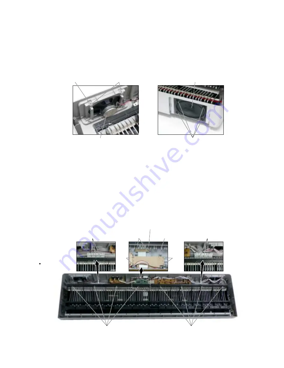
(Photo 7)
(Photo 8)
[S01]: Bind Head Tapping Screw-B 3.0x8 MFZN2W3 (WE774300)
Bタイト+BIND
[S02]: Bind Head Tapping Screw-B 3.0x25 MFZN2W3 (WE473400)
Bタイト+BIND
(Photo 9)
7.
Keyboard Assembly (Time Required: about 14 min)
7-1 Remove the lower case assembly. (See procedure 1.)
7-2 Remove the DM circuit board. (See procedure 2.)
7-3 Remove the two (2) screws marked [S01e]. The
cord binder can then be removed. (Photo 9)
7-4 Remove the four (4) screws marked [S01f]. The DM
protect sheet can then be removed. (Photo 9)
7-5 Remove the six (6) screws marked [S01g] and the
eight (8) screws marked [S02]. The keyboard assembly
can then be removed. (Photo 9)
7.
鍵盤Ass'y(所要時間: 約14分)
7-1.
下ケースAss'yを外します。
(
1
項参照)
7-2.
DMシートを外します。
(
2
項参照)
7-3. [S01e]
のネジ
2
本を外して、 GHL MK束線止め
を外します。(Photo 9)
7-4. [S01f]
のネジ
4
本を外して、 DMプロテクトシ
ートを外します。(Photo 9)
7-5. [S01g]
のネジ
6
本と
[S02]
のネジ
8
本を外して、
鍵盤Ass'yを外します。(Photo 9)
6.
Speaker (Time Required: about 14 min)
6-1 Remove the lower case assembly. (See procedure 1.)
6-2 Remove the two (2) screws marked [U60]. The speaker
grille assembly can then be removed. (Photo 2, 7)
6-3 Remove the four (4) screws marked [U40] . The speaker
can then be removed. (Photo 8)
6.
スピーカ(所要時間: 約14分)
6-1.
下ケースAss'yを外します。
(
1
項参照)
6-2. [U60]
のネジ
2
本を外して、SPグリルAss'yを外
します。
(
Photo 2, 7
)
6-3. [U40]
のネジ
4
本を外して、スピーカを外し
ます。(Photo 8)
Speaker(スピーカ)
Speaker grille(スピーカグリル)
[S01g]
[S01g]
[S02]
[S02]
Upper Case
(Inside view)
[U40]
[U60]
Speaker(スピーカ)
[S01e]
[S01f]
[S01f]
Cord binder(GHL MK束線止め)
DM protect sheet
(DMプロテクトシート)


