P-85/P-85S
6
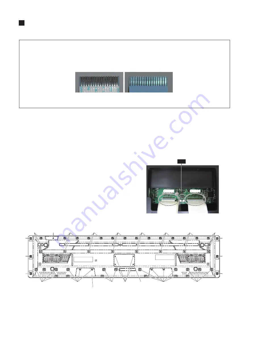
Fig. 1
(図 1)
[33]: Bind Head Tapping Screw-B(Bタイト+BIND)4.0X16 MFZN2W3 (WF154100)
[34]: Bind Head Tapping Screw-B(Bタイト+BIND)4.0X16 MFZN2B3 (WE998400)
[37]: Bind Head Tapping Screw-B(Bタイト+BIND)3.0X8 MFZN2B3 (WE774400)
DM
CN301
CN602
CN301
CN602
[33]
[34]
[33]
[33]
[33]
[33]
[33]
[33]
[33]
[33]
[33]
[33]
[33]
[33]
[33]
[37]
FFC Cover
(FFC カバー)
Lower case assembly
(下ケース Ass y)
[33]
[33]
[33]
[33]
[33]
<Bottom view>
Photo 2
(写真 2)
DISASSEMBLY PROCEDURE
(分解手順)
1.
Lower Case Assembly
(Time required: About 10 minutes)
1-1
Remove the four (4) screws marked [37]. The FFC
cover can then be removed. (Fig. 1)
1-2
Disconnect the connectors CN301 and CN602 on
the DM circuit board. (Photo 2)
1-3
Remove the fifty-seven (57) screws marked
[33] and the screw marked [34]. The lower case
assembly can then be removed. (Fig. 1)
1.
下ケース Ass'y
(所要時間:約 10 分)
1-1
[37] のネジ 4 本を外し、FFC カバーを外します。
(図 1)
1-2
DM シートのコネクタ CN301 と CN602 を外しま
す。
(写真 2)
1-3
[33] のネジ 57 本と [34] のネジ 1 本を外し、下ケー
ス Ass y を外します。
(図 1)
Caution:
1.
Be sure to attach the removed fi lament tape just
as it was before removal.
2.
Pay attention not to insert and install the cable
to the connector inversely. (Photo 1)
注意事項
1.
フィラメントテープは、取り外す前と同じように取
り付けてください。
2.
フラットケーブルの表・裏を逆に差し込まないよう
に注意して取り付けてください。(写真 1)
Front Side (Printed Side)
表面(印刷面)
Back Side
裏面
Photo 1
(写真 1)


