PF-1000
12
Circuit board and Assembly
Ref. No.
Screw
QTY Fig.
Shield Box Assembly
350A
Bind Head Tapping Screw-1 3.5x12 MFZN2Y (EP030240)
4
2
190
Bind Head Tapping Screw-B 3.0x8 MFZN2Y (EP600250)
6
2
SWX *1
100
Board Spacer
4
2
DM
150A
Bind Head Tapping Screw-B 3.0x8 MFZN2Y (EP600250)
5
2
Floppy Disk Drive Assembly
140A
Bind Head Tapping Screw-1 3.5x12 MFZN2Y (EP030240)
3
2
150B
Bind Head Tapping Screw-B 3.0x8 MFZN2Y (EP600250)
2
2
PNR
290A
Bind Head Tapping Screw-B 3.0x8 MFZN2Y (EP600250)
10
2
PNL
140B
Bind Head Tapping Screw-1 3.5x12 MFZN2Y (EP030240)
2
2
290B
Bind Head Tapping Screw-B 3.0x8 MFZN2Y (EP600250)
12
2
MV
Knob
1
290C
Bind Head Tapping Screw-B 3.0x8 MFZN2Y (EP600250)
3
2
ENC
Encoder Knob
1
290D
Bind Head Tapping Screw-B 3.0x8 MFZN2Y (EP600250)
3
2
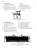
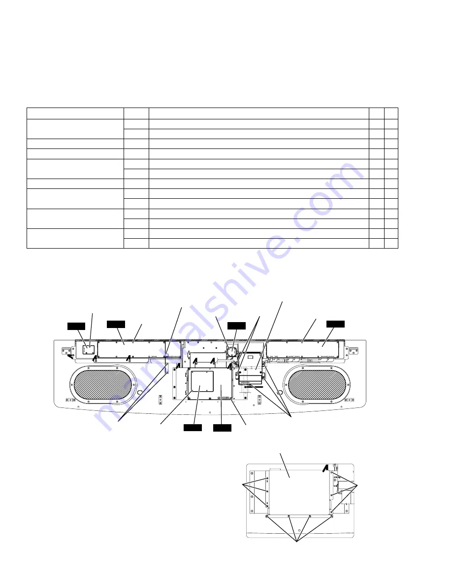
2.
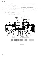
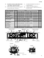
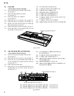
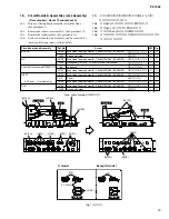
Circuit Boards & Assemblies (Top Board Assembly)
(Time required : About 7 minutes each)
2-1
Turn over the top board assembly toward the front.
(See procedure 1)
2-2
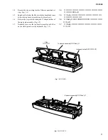
Each circuit board and assembly can be removed by
removing its fixing screws as listed below.
(Fig. 2)
PNL
ENC
PNR
SWX
DM
[290C] x 3
[290B] x 12
[290D] x 3
[150B]
[290A] x 10
[140A]
[150A] x 5
[100] x 4
[140B]
MV
[190]
[190]
[350A]
*1
Be careful of insertion position of spacer when you install the circuit board. Must not use spacer inserted in the reverse once.
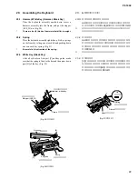
Floppy disk drive assembly
Shield box assembly
Panel stay assembly
2.
基板、
アッセンブリ
(屋根Ass y部)
(所要時間:各約7分)
2-1
屋根Ass yを前方へ裏返します。
(1項参照)
2-2
次のネジを外すことにより、
各基板・アッセンブリを外
すことができます。
+バインドTP1種
+バインドBタイト
ボードスペーサー
+バインドBタイト
+バインドTP1種
+バインドBタイト
+バインドBタイト
+バインドTP1種
+バインドBタイト
Vツマミ
+バインドBタイト
エンコーダツマミ
+バインドBタイト
(図2)
*1
取り付けるときは、ボードスぺーサーの向きに注意してください。一度でも逆差ししたスぺーサーは使用しないようにしてください。
(FDD Ass y)
(シールドボックス Ass y)
(FDD Ass y)
(シールドボックス Ass y)
(パネル金具Ass y)


