PF-1000
21
19.
Disassembling the Keyboard
*
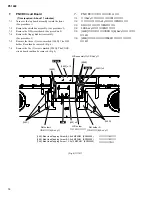
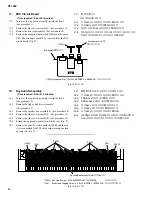
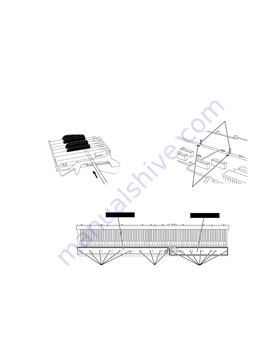
After inserting a round stick (Rod: TX000670) between the
frame and the keys, remove the circuit boards. (Fig. 14)
19-1
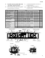
GH-D SW L Circuit Board
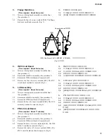
Remove the seven (7) screws marked [260A]. The GH-D
SW L circuit board can then be removed. (Fig. 15)
19-2
GH-D H Circuit Board
Remove the ten (10) screws marked [260B]. The GH-D
SW H circuit board can then be removed. (Fig. 15)
*
Keys can be removed without removing the circuit boards.
*
After removing the GH-D SW L and GH-D SW H circuit
boards, and the rubbers can then be removed.
(Fig. 14)
Round stick
(Rod: TX000670)
[260B]
[260B]
[260A]
GH-D SW H
GH-D SW L
(Fig. 15)
[260]: Bind Head Tapping Screw-P 3.0x10 MFZN2 (VT413400)
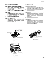
(Fig. 15-1)
Hooks
Triangle mark
19-4
White key
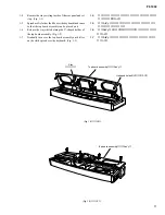
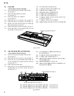
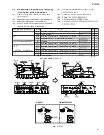
Insert a thin plate between the white keys, near the triangle
mark around the fulcrum of the key, and press down the
stopper marked [A] to remove the key.
(Fig. 16, Fig. 17)
*
Take care not to damage the key spring when removing a key.
*
A black key can be removed after the white keys on either
side have been removed.
19. GHD鍵盤の分解
※
シートをはずす前に、
接点ゴムを歪ませないように、
フレーム
とハンマーの間に丸棒
(ロッド:TX000670)
を挿入しておきま
す。
(図14)
19‐1 GH-D SW Lシート
[260A]のネジ7本を外し、
GH-D SW Lシートを外しま
す。
(図15)
19‐2 GH-D SW Hシート
[260B]のネジ10本を外し、
GH-D SW Hシートを外しま
す。
(図15)
※
白鍵と黒鍵は、GH-D SW Lシート、GH-D SW Hシートを外さ
なくても、外すことができます。
+バインドPタイト
(図15)
(丸棒)
(図14)
(図15-1)
(フック)
(三角マーク)
19‐4 白鍵
薄い金尺状のものを鍵盤の間に挿入して
(白鍵盤支点
付近の三角マークの示す方向側の隙間)[A]のストッ
パーを下げ、
白鍵を前方に少しずらして、
持ち上げて外
します。
(図16、
図17)
※
このとき、白鍵を前方にずらしすぎてスプリングを傷めない
ように十分注意して作業をしてください。
※
黒鍵は、両隣の白鍵を外すと、外すことができます。

