PF-1000
24
20-4
GH-D SW L Circuit Board
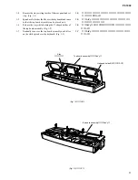
Tighten the seven (7) screws marked [260A] to fix
the GH-D SW L circuit board. (Fig. 15)
20-5
GH-D SW H Circuit Board
Tighten the ten (10) screws marked [260B] to fix the
GH-D SW H circuit board. (Fig. 15)
*
Install the circuit boards in the keyboard assembly so that
the hooks hold it as shown in figure 15-1.
21.
Disassembling the Pedal Unit
(Time required : About 5 minutes)
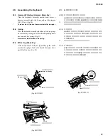
21-1
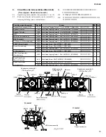
Remove the ten (10) screws marked [50C]. The pedal
cover assembly can then be removed. (Fig. 23)
21-2
Remove the two (2) screws marked [90B]. The pedal angle
assembly can then be removed. (Fig. 23)
21-3
Remove the two (2) screws marked [50D]. The pedal front
cover can then be removed. (Fig. 23)
21-4
Remove the ten (10) screws marked [50E]. The pedal
assembly can then be removed. (Fig. 23)
[50E]
[50E]
[50E]
[50E]
[50E]
[50D]
[50D]
[50C]
[50C]
[50C]
[90B]
[90B]
(Fig. 23)
[50]: Bind Head Tapping Screw-B 4.0x12 MFZN2BL (VR138400)
[90B]: Bind Head Tapping Screw-B 4.0x8 MFZN2Y (EP640410)
Pedal cover assembly
Pedal angle assembly
Pedal assembly
Pedal front cover
20-4 GH-D SW Lシート
GH-D SW Lシートを取り付け、
[260A]のネジ7本を取り
付けます。
(図15)
20-5 GH-D SW Hシート
GH-D SW Hシートを取り付け、
[260B]のネジ10本を取
り付けます。
(図15)
※
GH-D SW L/GH-D SW H基板シートを取り付ける際は、
フレー
ム裏側にあるフックと基板の△マークがあっていることを確
認してください。
(図15-1)
21. ペダルユニットの分解
(所要時間:約5分)
21‐1
[50C]のネジ10本を外し、
ペダルカバーAss yを外しま
す。
(図23)
21‐2
[90B]のネジ2本を外し、
ペダル金具Ass yを外します。
(図23)
21‐3
[50D]のネジ2本を外し、
ペダル前カバーを外します。
(図23)
21‐4
[50E]のネジ10本を外し、
ペダルAss y (P)を外します。
(図23)
(図23)
+バインドBタイト
+バインドBタイト
(ペダルAss y (P))
(ペダルカバーAss y)
(ペダル金具Ass y)
(ペダル前カバー)


