background image

6-23

6-22

6

Specifications

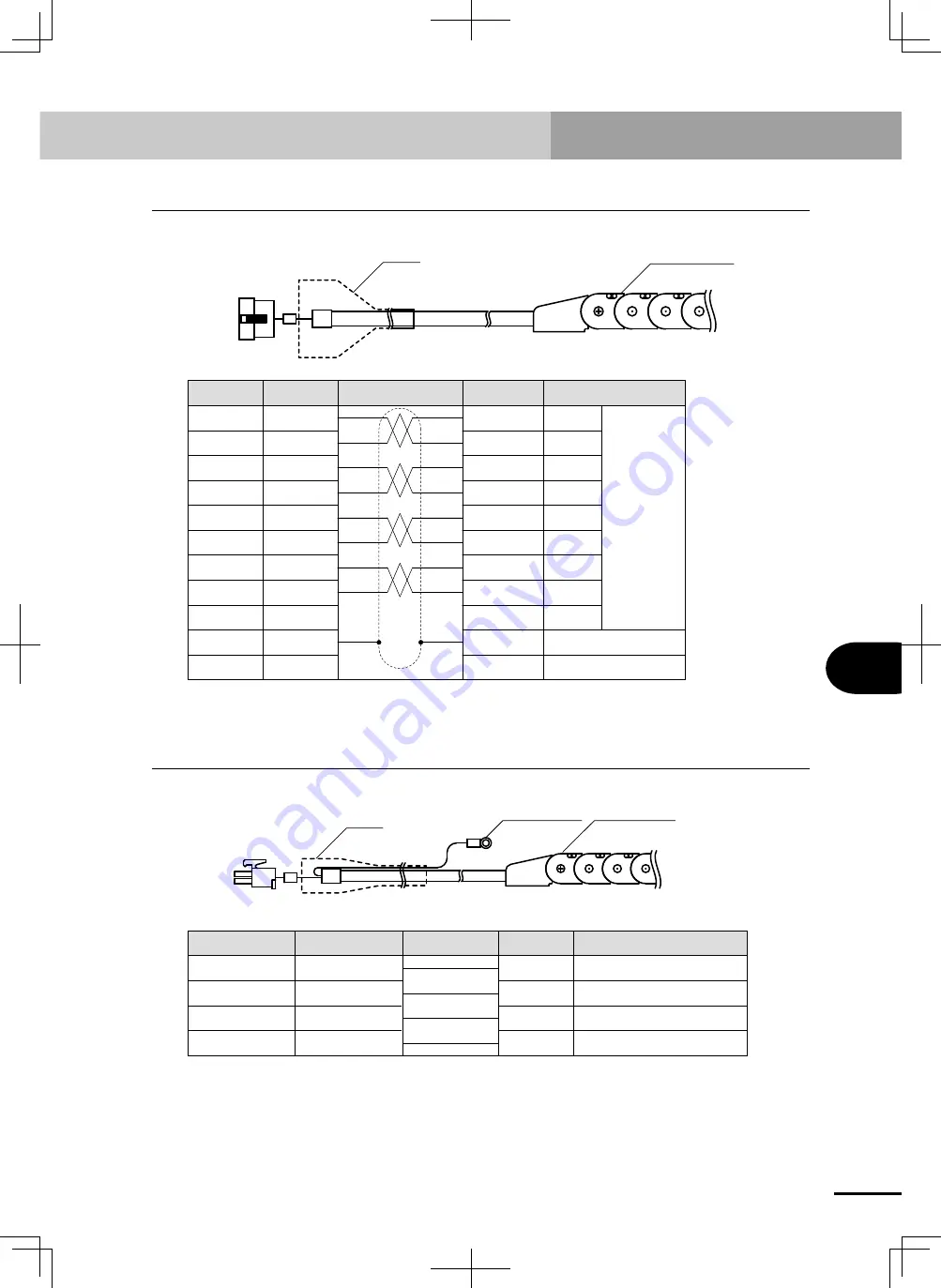
Robot connector (I/O signal connector)

2. 

Robot connector (I/O signal connector)

Cable carrier 

on robot

Hood

To robot cable 

(I/O signal wires)

D.G

6

5

4

3

2

1

Z-

Z+

S+

C+

C-

7

9

F.G

+5 V

S-

0.15mm

2


twisted pair

Shield

8

6

5

4

3

2

1

7

9

8

Signal

Connection

Remarks

Pin No.

Pin No.*

Blue

Orange

Green

Brown

Gray

Red

Black

Yellow

*Internally connected

3. 

Robot connector (motor connector)

Ground wire

Cable carrier 

on robot

Hood

To robot cable 

(motor wires)

3

2

1

4

3

2

1

0.5 mm

2

, 0.75mm

2

 Green

0.5 mm

2

, 0.75 mm

2

 Red

0.5 mm

2

, 0.75 mm

2

 White

0.5 mm

2

, 0.75 mm

2

 Black

Signal

Pin No.

Pin No.*

Connection

Remarks

Round terminal

Motor wire FG

U

W

V

*Internally connected

Summary of Contents for PHASER MF

Page 1: ...MF Type EUC021A540 E37 Ver 5 40 User s Manual YAMAHA LINEAR MOTOR ROBOTS PHASER series...

Page 2: ......

Page 3: ...ot 2 1 2 Robot installation conditions 2 2 2 1 Installation environments 2 2 2 2 Installation base 2 3 3 Installing the robot 2 5 4 Installing leakage breaker circuit protector 2 7 5 Protective bondin...

Page 4: ...ly inspection 4 4 2 2 Three month inspection 4 5 2 3 Six month inspection 4 6 2 4 Three year inspection 4 6 2 5 Greasing to the linear guides 4 7 3 Replacing the shutter 4 10 4 Replacing the shutter r...

Page 5: ...s 1 1 MF7 6 1 1 2 MF15 6 7 1 3 MF20 6 12 1 4 MF30 6 16 1 5 MF75 6 20 2 Robot connector I O signal connector 6 23 3 Robot connector motor connector 6 23 4 Robot cable I O signal wires 6 24 5 Robot cabl...

Page 6: ......

Page 7: ...andard models In this case refer to the specifications of standard models For details on specific operation of the robot refer to the separate user s manual for the robot controller being used 1 Avail...

Page 8: ...by everyone around the robot 3 Place a conspicuous sign prohibiting the operator or other personnel from entering the movement range of the manipulator To check the operation after setting refer to 4...

Page 9: ...an the above that are not the fault or responsibility of YAMAHA The following cases are not covered under the warranty 1 Products whose serial number or production date month year cannot be verified 2...

Page 10: ......

Page 11: ...Chapter 1 Product Overview Contents 1 Checking the product 1 1 2 Robot part names 1 2 3 Robot internal structure 1 3...

Page 12: ......

Page 13: ...le axis robot 1 Controller 1 Robot cable 1 I O connector 1 Warning label 1 DANGER label English and Japanese one each Stick the label at easy to see position of system Warning label 3 WARNING label En...

Page 14: ...rence The direction of the cables coming out of the cable carrier depends on the specifications you ordered The above illustration shows an example of RH right and horizontal type cCAUTION There are m...

Page 15: ...ut proper preparation is hazardous Also the required performance may not be obtained Magnet plate Linear motion guide PHASER series internal layout Moving coil internal Magnetic scale Magnetic head MF...

Page 16: ...d highly precise positioning cCAUTION Do not bring a strong magnet close to the magnetic scale A strong magnet may erase the information recorded on the scale and cause the robot to malfunction A magn...

Page 17: ...installation conditions 2 2 2 1 Installation environments 2 2 2 2 Installation base 2 3 3 Installing the robot 2 5 4 Installing leakage breaker circuit protector 2 7 5 Protective bonding 2 8 6 Connect...

Page 18: ......

Page 19: ...objects such as hands and grippers attached to the robot slider before moving the robot The slider will lose balance if moved with objects still attached and cause injuries Keep the robot balanced an...

Page 20: ...impacts or vibrations Working space Allow sufficient space margin to perform jobs teaching inspection repair etc For detailed information on how to install the robot controller refer to the separate...

Page 21: ...a sufficiently rigid and stable installation base taking into account the robot weight including the end effector gripper and workpiece wWARNING If the installation base is not sufficiently rigid and...

Page 22: ...llation base Bad example Installation base Robot installation example wWARNING When installing the robot always use all the installation holes or m8 tapped holes in the bottom of the robot frame Using...

Page 23: ...nstall the MF7 robot 1 Drill holes through the installation base and secure the robot to the base with M4 bolts from the bottom M4 tapped holes are already machined in the bottom of the robot frame Us...

Page 24: ...torque MF7 M4 hex socket head bolt Strength 8 8T Length installation base thickness 9 2 0 mm 30kgf cm to 45kgf cm MF15 MF20 MF30 M6 hex socket head bolt Strength 8 8T Length installation base thicknes...

Page 25: ...trical shocks injuries or fires might occur if the motor breaks down while the robot controller is used without installing a leakage breaker in the power supply section Electrical shocks injuries or f...

Page 26: ...al M4 screw for robot cable cCAUTION A secure ground connection less than 100 ohm resistance to ground is recommended Use electrical wire thicker than AWG14 2mm2 as the ground wire wWARNING Before mak...

Page 27: ...event unwanted movement of the motor power and signal wires wWARNING If the connectors are not securely inserted and the connector pins make poor contact the robot may malfunction causing hazardous si...

Page 28: ...es 2 After making the connections fit the connector hoods together securely Hood 3 Connect the robot cable ground terminal power and signal lines to the ground terminal on the robot frame MF7 MF7 MF15...

Page 29: ...1 P controller RS 232C communication control or Programming box HPB SD memory card Power supply General purpose input 8 points custom input 8 points General purpose output 5 points custom output 3 poi...

Page 30: ...eneral guide for cable and air tube installation The cables and air tubes inside the cable carrier will shift while the robot is operating becoming taut and placing a strain on the connectors at both...

Page 31: ...cification 3 1 1 3 Return to origin incremental specification 3 2 2 Setting operating conditions 3 4 2 1 Process flow for setting operating conditions 3 4 2 2 Duty monitor 3 5 2 3 Acceleration setting...

Page 32: ......

Page 33: ...e incremental and semi absolute specifications the magnetic pole estimation action is performed at servo on immediately after turning the power on 1 2 Absolute search semi absolute specification On th...

Page 34: ...he origin position is set on the L side prior to shipment The origin position can be set on the R side by changing the parameter See the separate SR1 Controller User s Manual for information on changi...

Page 35: ...the slider returns to the magnetic pole detection point There the slider moves in the reverse direction and re performs the operation in 1 This is not an equipment problem Direction of movement L sid...

Page 36: ...ils on the parameter setting method refer to the user s manual of the YAMAHA robot controller being used Set payload parameter Check actual operation duty check Does overload appear Is total cycle tim...

Page 37: ...itor allows you to easily check the current robot operating status to find out how hard the robot can still work versus overload criteria By checking the duty monitor you can repeatedly change the set...

Page 38: ...parameter value In the payload parameter set the total weight of the workpiece and the end effectors such as hands or grippers attached to the robot slider Acceleration can also be changed by paramete...

Page 39: ...s The current setting for PRM100 robot type appears on the screen Press the keys to scroll up or down the parameters until PRM112 payload is displayed 5 When PRM112 payload is displayed use the number...

Page 40: ...orms might adversely affect positioning accuracy and current value stability Acceleration deceleration and position proportional gain Acceleration deceleration and position proportional gain at differ...

Page 41: ...0 2 0 4 0 6 0 8 1 1 2 1 4 1 6 1 8 2 0 10 20 30 40 50 60 70 80 90 100 0 20 40 60 80 100 Payload kg Kpp Acceleration deceleration G Position proportional gain Kpp Acceleration G cCAUTION If the accelera...

Page 42: ...ain control the robot moves 1 micrometer per pulse To operate the robot at a maximum speed 2500 mm sec a pulse train at 2 5Mpps must be input The maximum speed might not be obtained depending on the o...

Page 43: ...4 5 2 3 Six month inspection 4 6 2 4 Three year inspection 4 6 2 5 Greasing to the linear guides 4 7 3 Replacing the shutter 4 10 4 Replacing the shutter roller 4 12 4 1 How to remove and replace the...

Page 44: ......

Page 45: ...or fence has not yet been provided right after installation of the robot rope off or chain off the movement area around the robot in place of a safety enclosure or fence and observe the following poi...

Page 46: ...care not to allow any foreign matter to contaminate them during adjustment parts replacement or reassembly Do not modify any parts on the robot or controller Modification may result in unsatisfactory...

Page 47: ...ach of children Do not heat the grease or place near an open flame since this could lead to sparks and fires Emergency Treatment If grease gets in the eyes wash liberally with pure water for about 15...

Page 48: ...at the duty ratio is less than 100 2 Inspection to be performed with the controller power turned on 1 Check that no one is inside the safety enclosure and then turn on the controller power 2 Place a s...

Page 49: ...ng precautions when performing 3 month inspection 1 Turn off the controller power 2 Place a sign indicating the robot is being inspected to keep others from operating the controller power 3 Enter the...

Page 50: ...r Check if terminals are loose Check if connectors are loose Greasing to linear guide Apply recommended grease to linear guide every 6 months Shutter Check for slack gap Adjust if necessary Refer to 3...

Page 51: ...ller power 3 Place a sign indicating the robot is being inspected to keep others from operating the controller power 4 Enter the safety enclosure 5 Apply grease by either of the following methods 1 Re...

Page 52: ...oller power 3 Place a sign indicating the robot is being inspected to keep others from operating the controller power 4 Enter the safety enclosure 5 Apply grease by either of the following methods 1 I...

Page 53: ...controller power 4 Enter the safety enclosure 5 Apply grease by either of the following methods 1 Remove the four screws on the end face of the robot and remove the end cover 2 Move the slider carriag...

Page 54: ...both shutter clamp plates located at the ends of the robot body Shutter clamp plate MF50 MF50 2 Fasten the new shutter onto the old shutter for replacement with tape as shown in the photo Old shutter...

Page 55: ...ose from the groove in the stroke cover and draw in the new shutter Be careful at this time not to let the new shutter twist warp or hang up MF50 MF50 MF50 MF50 4 After finished installing the new shu...

Page 56: ...he other MF series robots the carried object must be removed Loctite thread locking agent has been applied to the 8 screws which secure the slider cover Use care to avoid stripping the thread of the s...

Page 57: ...the shutter Flat head screw M3X6L Shutter roller outer Shutter roller inner This is inside the shutter and will not appear until the flat head screws are removed 4 2 Attaching the shutter roller For M...

Page 58: ...touch each other carry out 4 3 Adjusting shutter tension For MF7 4 After confirming 3 attach another slider cover 4 3 Adjusting shutter tension For MF7 Remove one side of the slider cover and loosen...

Page 59: ...ding the slider cover and remove the slider cover Slider cover 3 Remove the two screws one on each side holding the shutter roller and remove the shutter roller 4 Install the new shutter roller and pl...

Page 60: ...BW M22LK X0 MF15 Stroke 3100 or longer KBW M225M X0 MF15D Stroke up to 2800 KBW M225N X0 MF15D Stroke 2900 or longer MF20 MF30 Part name Part No Remarks Shutter KBS M229J X0 MF20 Stroke up to 3050 MF3...

Page 61: ...Chapter 5 Troubleshooting Contents 1 If you suspect trouble 5 1 2 Feedback error 5 1 3 Magnetic pole detection error 5 3 4 Overload 5 4 5 Position deviation error 5 5...

Page 62: ......

Page 63: ...off and check slider movement by moving it by hand Check wiring by referring to robot manual Check robot number on HPB screen while referring to SR1 controller user s manual If replacement controller...

Page 64: ...n display Check robot number on HPB screen while referring to SR1 controller user s manual Motor resistance is abnormal Repair Repair Replace the cable Current position display on HPB fluctuates Secur...

Page 65: ...y hand Check wiring by referring to robot manual Robot mechanical movement is heavy at point where power is turned on Repair the robot Correct wiring or replace defective connector pins Connector wiri...

Page 66: ...riction Motor cable is broken or frayed Motor resistance is abnormal Check operating conditions by referring to the manual Take noise reduction measures Initialize parameters Robot number parameter is...

Page 67: ...e mechanical parts 1 Check tool and workpiece for warping 2 Check robot alignment Are cables correctly wired Are connectors correctly fitted Are the robot tools and workpiece correctly installed Yes Y...

Page 68: ...5 6 MEMO...

Page 69: ...1 Main unit 6 1 1 1 MF7 6 1 1 2 MF15 6 7 1 3 MF20 6 12 1 4 MF30 6 16 1 5 MF75 6 20 2 Robot connector I O signal connector 6 23 3 Robot connector motor connector 6 23 4 Robot cable I O signal wires 6...

Page 70: ......

Page 71: ...10 7 Rated thrust N 37 Maximum stroke mm 4000 2000 3800 1800 Linear guide 4 rows of circular arc grooves 1 rail Maximum cross section outside dimensions mm W85 H80 excluding cable carrier Overall len...

Page 72: ...g carried This is calculated assuming that the service life of the guide is 10 000km Horizontal installation A C B Unit mm A B C 1kg 3000 3000 680 3kg 3000 1350 215 5kg 2900 830 125 7kg 2400 580 85 9k...

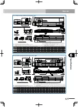
Page 73: ...all mount model 50 80 190 65 79 142 L 110 50 Note 3 140 Effective stroke 140 140 5 L side origin position 58 7 64 5 84 8 6 180 9 Note 4 79 G S type Standard and S types 20 180 9 Note 4 99 5 Optional c...

Page 74: ...e R side by parameter setting Note The drawings on this page show the unit with horizontal right type cable carrier RH Note For models with a 3 000mm or longer stroke a roller is installed to prevent...

Page 75: ...80 50 65 79 50 80 190 110 110 79 65 142 142 L 50 Note 2 50 Note 2 Effective stroke Effective stroke Standard and S types Standard and M types Standard and L types 40 100 A x 100 40 50 90 F F 2 6 11 6...

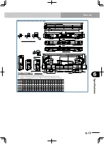
Page 76: ...round terminal M4 30 0 02 50 80 65 79 L 4 4H7 Depth 10 8 M5 0 8 Depth 12 190 110 40 1 Note 2 40 1 Note 2 Effective stroke 140 5 Note 1 Effective stroke 140 5 Note 1 200 Minimum distance between carria...

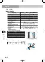
Page 77: ...ed thrust N 54 Maximum stroke mm 4000 2000 3800 1800 Linear guide 4 rows of circular arc grooves 2 rail Maximum cross section outside dimensions mm W100 H80 excluding cable carrier Overall length mm S...

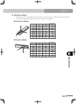
Page 78: ...lated assuming that the service life of the guide is 10 000km Horizontal installation A C B Unit mm A B C 5kg 3000 3000 915 10kg 2604 1542 481 15kg 2368 1051 340 20kg 1820 600 260 25kg 1470 450 175 30...

Page 79: ...9 10 10 11 11 12 12 13 13 14 14 15 15 16 16 17 17 18 18 19 19 20 20 21 C 6 8 8 10 10 12 12 14 14 16 16 18 18 20 20 22 22 24 24 26 26 28 28 30 30 32 32 34 34 36 36 38 38 40 40 42 42 44 D 400 500 600 7...

Page 80: ...the L side by parameter setting Note Protrusion is the distance the cable carrier extends from the edge of unit when an optional L type cable carrier is used Note When using 10 H7 hole do not insert...

Page 81: ...determined by the mechanical stoppers at both ends Note Protrusion is the distance the cable carrier extends from the edge of unit when an optional L type cable carrier is used Note When using 10 H7...

Page 82: ...ted thrust N 86 Maximum stroke mm 4050 3850 Linear guide 4 rows of circular arc grooves 2 rail Maximum cross section outside dimensions mm W150 H80 excluding cable carrier Overall length mm Stroke len...

Page 83: ...the service life of the guide is 10 000km Horizontal installation A C B Unit mm A B C 10kg 3156 1747 1196 15kg 2811 1176 883 20kg 2679 890 717 25kg 2190 720 505 30kg 1830 605 370 35kg 1580 525 275 40...

Page 84: ...1024102510261027102810291030103110321033103410351036103710381039104010411042104310 A 105 55 105 55 105 55 105 55 105 55 105 55 105 55 105 55 105 55 105 55 105 55 105 55 105 55 105 55 105 55 105 55 105...

Page 85: ...250335034503550365037503850 L 610 710 810 910 1010111012101310141015101610171018101910201021102210231024102510261027102810291030103110321033103410351036103710381039104010411042104310 A 105 55 105 55 1...

Page 86: ...0 Rated thrust N 125 Maximum stroke mm 4000 3750 Linear guide 4 rows of circular arc grooves 2 rail Maximum cross section outside dimensions mm W150 H80 excluding cable carrier Overall length mm Strok...

Page 87: ...lated assuming that the service life of the guide is 10 000km Horizontal installation A C B Unit mm A B C 10kg 3364 2485 1284 20kg 2298 1265 694 30kg 2060 859 507 40kg 1570 600 310 50kg 1265 400 180 6...

Page 88: ...24102510261027102810291030103110321033103410351036103710381039104010411042104310 A 105 55 105 55 105 55 105 55 105 55 105 55 105 55 105 55 105 55 105 55 105 55 105 55 105 55 105 55 105 55 105 55 105 5...

Page 89: ...2850295030503150325033503450355036503750 L 710 810 910 1010 1110 12101310141015101610171018101910201021102210231024102510261027102810291030103110321033103410351036103710381039104010411042104310 A 55 1...

Page 90: ...ooves 2 rail Maximum cross section outside dimensions mm W210 H100 excluding cable carrier Overall length mm Stroke length 360 Stroke length 680 Cable length m Standard 3 5 Option 5 10 Controller SR1...

Page 91: ...he gravity center of the item being carried This is calculated assuming that the service life of the guide is 10 000km Horizontal installation A C B Unit mm A B C 20kg 3397 2841 1840 40kg 2795 1389 96...

Page 92: ...560 1660 1760 1860 1960 2060 2160 2260 2360 2460 2560 2660 2760 2860 2960 3060 3160 3260 3360 3460 3560 3660 3760 3860 3960 4060 4160 4260 4360 A 180 230 80 130 180 230 80 130 180 230 80 130 180 230 8...

Page 93: ...8 6 5 4 3 2 1 7 9 8 Signal Connection Remarks Pin No Pin No Blue Orange Green Brown Gray Red Black Yellow Internally connected 3 Robot connector motor connector Ground wire Cable carrier on robot Hood...
Page 94: ...Gray Red Black Yellow 5 1 3 8 2 7 4 20 6 Z C S C S Z FG 5V D G Round terminal 5 Robot cable motor wires Ground wire Hood To controller To robot n SR1 SRCP Motor wire FG U V W 0 75 mm2 Yellow Green 0 7...

Page 95: ...correction of Chapter 5 Periodic inspection and maintenance Clerical error corrections Ver 4 00 Aug 2010 Addition of descriptions regarding the addition of MF7 Clerical error corrections Ver 5 00 Jul...

Page 96: ......

Page 97: ...Robot manuals can be downloaded from our company website Please use the following for more detailed information YAMAHA MOTOR CO LTD Robotics Operations 127 Toyooka Kitaku Hamamatsu Shizuoka 433 8103...

Reviews: