87
Appendix
Mono Input Module
Stereo Input Module
5
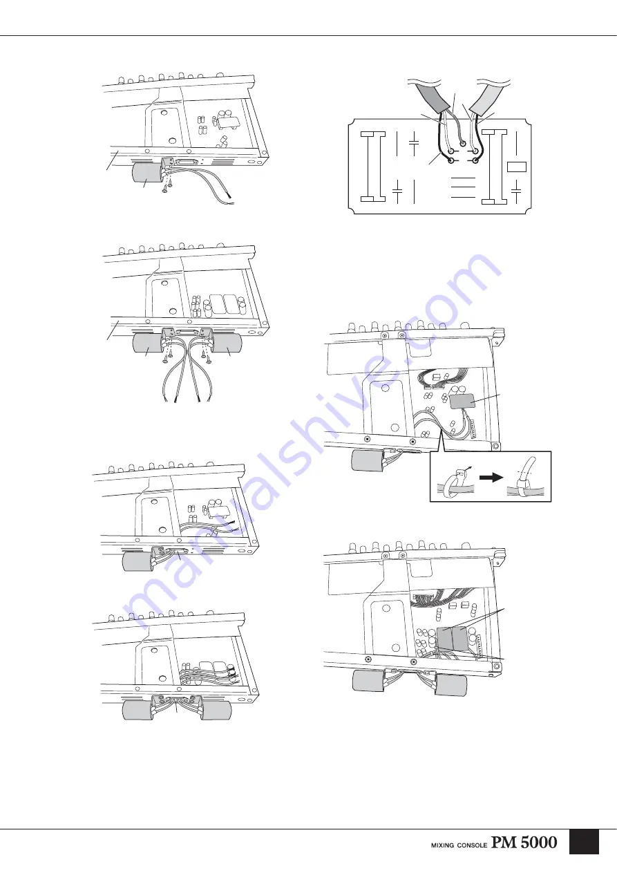
Pass the transformer leads through the square lead hole.
Mono Input Module
Stereo Input Module
6
The transformer leads must now be soldered to the
small circuit board included in the ITR5000 package.
One circuit board is used for each transformer on
stereo modules. The leads must be soldered to the
circuit board as shown in the illustration below.
7
Remove (unplug) the existing small circuit board
from the module, and replace it with the circuit board
now soldered to the transformer leads. Next, neatly
tie the transformer leads using the supplied cable tie,
and cut off the excess tie.
Mono input module
Stereo input module
8
Make sure the transformer leads are completely
contained within the module.
That completes transformer installation.
Be careful that the leads don’t get caught on any part of
the console when installing or later removing the
module.
Transformer
Bottom stay
Transformer
Transformer
Bottom stay
Lead hole
Lead hole
CN201
CN202
IN5
YAMAHA
R119
R260
C183
R119
C114
C113
XK367
R106
R104
R105
J6
J6
1
4
2
5
3
Red
Red
White
White
Shield
Transformer leads
Brown
Brown
Red
Red
Replace this
circuit board
Tie the transformer
leads with the cable tie
Tie through the holes
Cut
Replace these
two circuit
boards
Tie the leads in
the same way
as shown above
Summary of Contents for PM 5000 Series
Page 1: ...Owner s Manual E ...


