6.13 Stereo Input Module: Output
Enable Jumpers to Group, Stereo
and Aux Busses
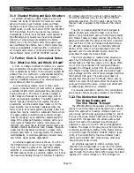
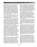
The stereo input module may be used as an effects
return module. In this case, it could be disastrous if an
incoming signal were to be assigned to the bus which is
feeding the signal processor whose output is coming into
the module. In other words, at the press of the wrong
bus-assign button, there could be feedback that might
stereo bus, or the aux busses. As shipped from the
factory, internal jumpers (headers) on the module carry
the signals to these busses. You can “cut” one pair of
jumpers to positively kill the module’s output to the
eight group busses by moving the header (two-pin clip)
to the position which does not complete the circuit to the
output; another pair of jumpers kill the output to the
stereo bus; another three pair of jumpers kill the post-
fader, pre-EQ and post-EQ feeds to the aux busses.
These jumpers are identified in Figure 6-13.
shatter eardrums and shred loudspeakers. Careful
operation can avoid this problem, but it cannot abso-
lutely prevent it. Therefore, you may wish to disable a
given stereo module’s output to the group busses, the
NOTE: Should you wish to reactivate a module’s output
to a given bus, you can always restore the jumpers so the
are as originally shipped.
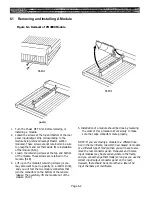
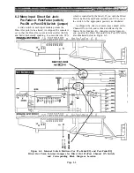
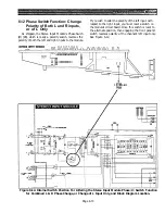
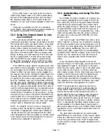
Figure 6-13. Internal Switch Positions For Pre- and Post- Group Master Fader Feeds to Mix Matrix,
and Block Diagram Location.
Page 6-14
Summary of Contents for PM4000
Page 1: ...PROFESSIONAL AUDIO MIXING CONSOLE PM4000 OPERATING MANUAL YAMAHA ...
Page 2: ...PM4000 OPERATING MANUAL ...
Page 7: ...Section 1 Introduction ...
Page 11: ...Section 2 Brief Operating Instruction ...
Page 47: ...Section 3 Specifications ...
Page 51: ...Dimensional Drawings PM4000 Console all versions Page 3 4 ...
Page 52: ...Page 3 5 ...
Page 53: ...Page 3 6 PM4000 Console Rear Profiles ...
Page 54: ...Module Block Diagrams See back of the manual for overall system block diagram Page 3 7 ...
Page 55: ...Page 3 8 ...
Page 56: ...Page 3 9 ...
Page 57: ...Page 3 10 ...
Page 58: ...Page 3 11 ...
Page 59: ...Page 3 12 ...
Page 60: ...Section 4 Installation Notes ...
Page 72: ...Figure 4 13 Cables For Use With Balanced Sources Page 4 12 ...
Page 79: ...SECTION 5 Gain Structure and Levels ...
Page 82: ...Figure 5 1 Dynamic Range and Headroom in Sound Systems Page 5 3 ...
Page 86: ...Section 6 Optional Functions ...
Page 106: ...Section 7 Operating Notes and Hints ...
Page 119: ...Section 8 Applications ...
Page 127: ...Section 9 Maintenance ...
Page 131: ......
Page 132: ...YAMAHA VN02300 ...


