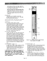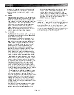
TOM POWER switch is on. An LED in the switch
turns on when phantom power is being applied to
the channel input connector.
When both the Master and this switch are on,
+48 volts is applied to both pins 2 & 3 of the
channel input XLR connector for remote power-
ing of condenser microphones. Although phantom
power will not harm most dynamic and other
non-phantom powered microphones or line-level
devices, connection of an unbalanced source to
the channel input could partially short the
console’s phantom supply, cause undue loading,
and induce hum. Therefore, it is a good practice
to turn off the channel’s phantom power unless it
is actually in use.
NOTE: The console's microphone power supply is not
intended for A-B powered microphones. External sup-
plies may be used with these devices, in which case the
console’s phantom power should be turned OFF on the
appropriate channels. The optional input transformers,
if installed, do not affect phantom power operation.
5
.
GAIN
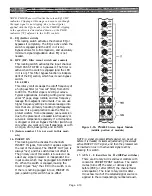
This rotary knob provides 50 dB of continuously
variable adjustment for the input preamplifier
gain. A setting of -70 (full clockwise rotation)
provides maximum gain for low-level mic inputs,
whereas a setting of -20 provides minimum gain
for low-level line inputs or “hot” mics. These
settings provide 30 dB less overall gain when 30
dB pad is engaged [6].
6.
30 dB (pad switch)
Engaging this pushbutton switch attenuates the
signal 30 dB and turns on an LED in the switch.
The PAD should be used in conjunction with the
GAIN control to obtain the precise channel
sensitivity necessary for a given source. If you’re
not sure whether an input is high line level or
mic level, begin with the pad engaged, and the
GAIN control at -20 (+10) position. Then rotate
the GAIN control clockwise. If you still don’t get
enough level, or if the signal is noisy with a lot of
gain, then turn down the GAIN, disengage the
pad and reset the GAIN control as necessary.
NOTE: By adjusting the GAIN control, you may be able
to get the same overall level with or without the pad
engaged. Listen for noise and distortion, though; if the
signal is noisy, don’t use the pad. If there is a lot of
distortion, use the pad.
Front
Bandwidth
panel
Q
(octave)
3.0 0.5
1.4 1.0
center position 1.2 1.2
0.7 2.0
0.5 2.5
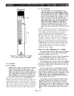
7. PEAK
This red LED turns on to indicate when the
signal present after the channel preamp is too
high in level. The LED triggers 3 dB below
clipping, and should therefore flash on only
occasionally.
This indicator measures signal from the XLR or
from the INSERT IN jack, whichever is active, as
well as after the equalizer. If necessary, use the
PAD or decrease the GAIN setting to prevent the
LED from remaining on any longer than momen-
tarily; otherwise excessive distortion and insuffi-
cient fader travel will result.
8. Ø (Phase)
This switch reverses the polarity of pins 2 and 3
of the channel’s XLR input connector. In normal
position (switch button up), pin 2 is the signal
high conductor, and in reverse position (switch
engaged), pin 3 is high. An LED in the switch is
illuminated when polarity is reversed.
This eliminates the need to rewire connectors or
use adapters for out-of-phase (reversed polarity)
audio sources. Sometimes intentional polarity
reversal can be helpful in canceling leakage from
adjacent microphones, or in creating electro-
acoustic special effects by mixing together out-of-
phase signals from mics picking up the same
sound source.
EQUALIZER
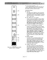
The input channel equalizer is divided into four
bands, each with sweepable filter frequencies.
The high and low bands may be switched for a
peaking or shelving type curve, whereas the high-
mid and low-mid bands are of the peaking type.
All four bands have adjustable Q, providing fully
parametric type EQ. The level (gain) is adjustable
over a range of 15 dB boost and 15 dB cut in each
band.
9. HIGH (Peak/Shelf)
This locking switch selects peaking type EQ
(switch out) or shelving type EQ (switch en-
gaged). When the switch is engaged (shelving
mode), the adjacent Q control is not operational.
Q
This rotary control adjusts the Q (the bandwidth)
of this section of the equalizer from a very narrow
band to a very broad band, with a center detent
at a Q of 1.2.
Page 2-2
Channel EQ “Q” Characteristics
Summary of Contents for PM4000
Page 1: ...PROFESSIONAL AUDIO MIXING CONSOLE PM4000 OPERATING MANUAL YAMAHA ...
Page 2: ...PM4000 OPERATING MANUAL ...
Page 7: ...Section 1 Introduction ...
Page 11: ...Section 2 Brief Operating Instruction ...
Page 47: ...Section 3 Specifications ...
Page 51: ...Dimensional Drawings PM4000 Console all versions Page 3 4 ...
Page 52: ...Page 3 5 ...
Page 53: ...Page 3 6 PM4000 Console Rear Profiles ...
Page 54: ...Module Block Diagrams See back of the manual for overall system block diagram Page 3 7 ...
Page 55: ...Page 3 8 ...
Page 56: ...Page 3 9 ...
Page 57: ...Page 3 10 ...
Page 58: ...Page 3 11 ...
Page 59: ...Page 3 12 ...
Page 60: ...Section 4 Installation Notes ...
Page 72: ...Figure 4 13 Cables For Use With Balanced Sources Page 4 12 ...
Page 79: ...SECTION 5 Gain Structure and Levels ...
Page 82: ...Figure 5 1 Dynamic Range and Headroom in Sound Systems Page 5 3 ...
Page 86: ...Section 6 Optional Functions ...
Page 106: ...Section 7 Operating Notes and Hints ...
Page 119: ...Section 8 Applications ...
Page 127: ...Section 9 Maintenance ...
Page 131: ......
Page 132: ...YAMAHA VN02300 ...


