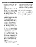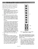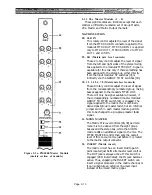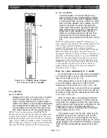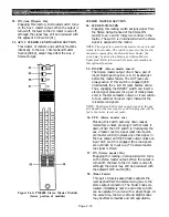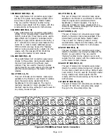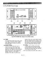
Figure 2-5b. PM4000 TB Module
(middle portion of module)
oscillator when it is not actually in use.
NOTE: Even though the oscillator may not be assigned
to any busses, it is still possible that you would inadvert-
ently select it when preparing to use the talkback feature,
or that some signal could leak into busses (albeit at low
levels). Hence, leave the oscillator OFF when it is not
actually being used for testing or calibration.
67. PINK 10K 1K 100 OFF
These 5 interlocking switches set the oscillator to
100 Hz, 1 kHz or 10 kHz operation when the
nearby SWEEP switch is in fixed frequency
position (disengaged). They also permit selection
of a pink noise source, or turn off the oscillator/
noise source altogether.
68. SWEEP (switch and rotary control)
Engaging the SWEEP switch removes the oscilla-
tor from its fixed frequency mode (i.e., generating
exactly 100 Hz, 1 kHz or 10 kHz). The nearby
rotary control then may be used to adjust the
oscillator output from approximately 0.2 to 2
times the set “fixed” frequency. For example,
when the oscillator is set for 10K Hz (switch [67]),
the sweep mode enables you to adjust the actual
oscillator frequency between 2 kHz and 20 kHz.
69. LEVEL OSC
This rotary control adjusts the oscillator output
level applied to the OSC OUT connector as well
as any mixing busses to which the signal may be
assigned. This control does not affect the
Talkback level.
70. +48V
This switch turns phantom power on and off in
the XLR Talkback Input connector. Power can be
turned on, however, only if the MASTER PHAN-
TOM POWER switch is on. An LED in the switch
turns on when phantom power is being applied to
the TB input.
When both the Master and this switch are on,
+48 volts is applied to both pins 2 & 3 of the TB
input XLR connector for powering a condenser
microphone. Although phantom power will not
harm most dynamic and other non-phantom
powered microphones or line-level devices,
connection of an unbalanced, source to the chan-
nel input could partially short the console’s
phantom supply, cause undue loading, and
induce hum. Therefore, it is a good practice to
turn off the TB phantom power unless it
is
actually in use.
NOTE: The console’s microphone power supply is not
intended for A-B powered microphones. Use an external
Page 2-20
Summary of Contents for PM4000
Page 1: ...PROFESSIONAL AUDIO MIXING CONSOLE PM4000 OPERATING MANUAL YAMAHA ...
Page 2: ...PM4000 OPERATING MANUAL ...
Page 7: ...Section 1 Introduction ...
Page 11: ...Section 2 Brief Operating Instruction ...
Page 47: ...Section 3 Specifications ...
Page 51: ...Dimensional Drawings PM4000 Console all versions Page 3 4 ...
Page 52: ...Page 3 5 ...
Page 53: ...Page 3 6 PM4000 Console Rear Profiles ...
Page 54: ...Module Block Diagrams See back of the manual for overall system block diagram Page 3 7 ...
Page 55: ...Page 3 8 ...
Page 56: ...Page 3 9 ...
Page 57: ...Page 3 10 ...
Page 58: ...Page 3 11 ...
Page 59: ...Page 3 12 ...
Page 60: ...Section 4 Installation Notes ...
Page 72: ...Figure 4 13 Cables For Use With Balanced Sources Page 4 12 ...
Page 79: ...SECTION 5 Gain Structure and Levels ...
Page 82: ...Figure 5 1 Dynamic Range and Headroom in Sound Systems Page 5 3 ...
Page 86: ...Section 6 Optional Functions ...
Page 106: ...Section 7 Operating Notes and Hints ...
Page 119: ...Section 8 Applications ...
Page 127: ...Section 9 Maintenance ...
Page 131: ......
Page 132: ...YAMAHA VN02300 ...

