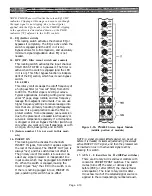
81. ON switch (Monitor B On)
Engaging this switch applies the Monitor B
signal to the Monitor B left and right output
connectors. The switch is illuminated when the
output is on.
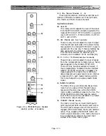
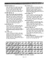
Figure 2-6b. PM4000 Monitor Module
(middle portion of module)
82. 2TR IN 1, 2TR, IN 2, ST CH3, ST CH4, ST OUT
(Monitor A Source Select Switches)
These five switches function just like the first five
Monitor B Source Select switches [78], except
they send signal to the Monitor A outputs.
83. AUX ST 1, AUX ST2 (Monitor A Source Select
Switches)
These two switches provide still more choices for
driving the Monitor A output, selecting from the
AUX ST 1 master output or AUX ST 2 master
output (post-fader and post-on/off switch).
84. AUX, GROUP, MTRX (Monitor A Source
Select Switches)
These three switches provide many more choices
for driving the Monitor A output, selecting from
the auxiliary, group or matrix outputs (post-
master faders and post-on/off switches). There
are eight possible busses you can monitor in each
of these three groupings, and they are divided
into four stereo pairs (see bus group selectors
[85]
below).
85. 1-2, 3-4, 5-6, 7-8 (Aux/Group/Mtrx bus group
selectors)
Pressing one of these four switches selects the
bus pair which the associated AUX, GROUP or
MTRX switch [84] will feed to the Monitor A
output.
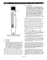
86. LEVEL (Monitor A level control)
This rotary control sets the level of the signal
going to the Monitor A left and right output
connectors.
87. CUE (Indicator)
This red LED turns on when the cue system has
been activated as a reminder that previously
selected monitor A signal has replaced whatever
signal(s) you may have selected for with one or
more of the console’s CUE switches.
88. MONO (Monitor A mode)
Engaging this locking switch combines the left
and right sides of the monitor A signal and feeds
the combined mono signal to the left and right
monitor A outputs. The LED in the switch is
illuminated when mono monitoring is active. It is
useful for checking the mono compatibility of a
stereo program signal.
89. ON (Monitor A On)
Engaging this switch applies the Monitor A
signal to the Monitor A left and right output
connectors. The switch is illuminated when the
output is on.
Page 2-23
Summary of Contents for PM4000
Page 1: ...PROFESSIONAL AUDIO MIXING CONSOLE PM4000 OPERATING MANUAL YAMAHA ...
Page 2: ...PM4000 OPERATING MANUAL ...
Page 7: ...Section 1 Introduction ...
Page 11: ...Section 2 Brief Operating Instruction ...
Page 47: ...Section 3 Specifications ...
Page 51: ...Dimensional Drawings PM4000 Console all versions Page 3 4 ...
Page 52: ...Page 3 5 ...
Page 53: ...Page 3 6 PM4000 Console Rear Profiles ...
Page 54: ...Module Block Diagrams See back of the manual for overall system block diagram Page 3 7 ...
Page 55: ...Page 3 8 ...
Page 56: ...Page 3 9 ...
Page 57: ...Page 3 10 ...
Page 58: ...Page 3 11 ...
Page 59: ...Page 3 12 ...
Page 60: ...Section 4 Installation Notes ...
Page 72: ...Figure 4 13 Cables For Use With Balanced Sources Page 4 12 ...
Page 79: ...SECTION 5 Gain Structure and Levels ...
Page 82: ...Figure 5 1 Dynamic Range and Headroom in Sound Systems Page 5 3 ...
Page 86: ...Section 6 Optional Functions ...
Page 106: ...Section 7 Operating Notes and Hints ...
Page 119: ...Section 8 Applications ...
Page 127: ...Section 9 Maintenance ...
Page 131: ......
Page 132: ...YAMAHA VN02300 ...


