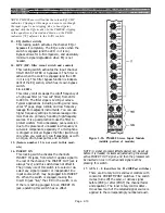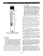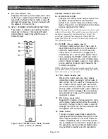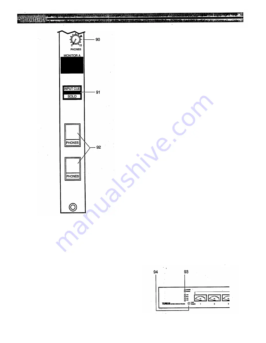
90. PHONES (Level control)
This 2-gang rotary control adjust the output level
at both stereo PHONES output jacks. It affects
any signals which may be fed to these outputs.
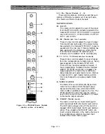
91. INPUT CUE / SOLO
(LED status annunciators)
INPUT CUE is a yellow LED that turns on when
any input channel’s CUE/SOLO switch is en-
gaged, indicating the console is subject to input
cue priority. This is an indication that the signal
in the monitor A and the headphones outputs is
being derived from one or more inputs via the cue
system. The indicator operates the same whether
the console is in cue or solo mode.
SOLO is a red LED that flashes if the console is
in the SOLO mode. This serves as an urgent
warning that if any input CUE/SOLO switch is
depressed, that all input channels will be muted
except the soloed channel(s).
CAUTION: If the red SOLO LED is flash-
ing during a performance, DO NOT press
any input CUE/SOLO switch Instead,
disengage the SOLO MODE switch [77].
This will prevent program interruption
when attempting to cue an input.
92. PHONES (Output jacks)
This pair of ¼" (6.33mm) stereo phone jacks can
accommodate two pair of standard 8-ohm or
higher impedance stereo headphones. The jacks
are recessed behind spring-loaded cover panels
which exclude dust when the jacks are not in use.
The jacks are also angled to minimize strain on
cables and connectors.
Figure 2-6c. PM4000 Monitor Module
(lower portion of module)
Page 2-24
Summary of Contents for PM4000
Page 1: ...PROFESSIONAL AUDIO MIXING CONSOLE PM4000 OPERATING MANUAL YAMAHA ...
Page 2: ...PM4000 OPERATING MANUAL ...
Page 7: ...Section 1 Introduction ...
Page 11: ...Section 2 Brief Operating Instruction ...
Page 47: ...Section 3 Specifications ...
Page 51: ...Dimensional Drawings PM4000 Console all versions Page 3 4 ...
Page 52: ...Page 3 5 ...
Page 53: ...Page 3 6 PM4000 Console Rear Profiles ...
Page 54: ...Module Block Diagrams See back of the manual for overall system block diagram Page 3 7 ...
Page 55: ...Page 3 8 ...
Page 56: ...Page 3 9 ...
Page 57: ...Page 3 10 ...
Page 58: ...Page 3 11 ...
Page 59: ...Page 3 12 ...
Page 60: ...Section 4 Installation Notes ...
Page 72: ...Figure 4 13 Cables For Use With Balanced Sources Page 4 12 ...
Page 79: ...SECTION 5 Gain Structure and Levels ...
Page 82: ...Figure 5 1 Dynamic Range and Headroom in Sound Systems Page 5 3 ...
Page 86: ...Section 6 Optional Functions ...
Page 106: ...Section 7 Operating Notes and Hints ...
Page 119: ...Section 8 Applications ...
Page 127: ...Section 9 Maintenance ...
Page 131: ......
Page 132: ...YAMAHA VN02300 ...

