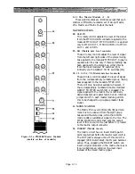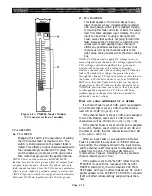
96. II (Group/Matrix/Aux meters and indicators)
97. ST L, ST R (Stereo output meters)
On 24 and 32 channel mainframes, these four
meters monitor the correspondingly numbered
busses, as described above in item [95].
In 40 or 48 channel mainframes, these eight
meters display the eight group outputs or the
eight matrix outputs (redundant with the first
two selections for the I set of meters [95]), or the
aux outputs. This AUX selection differs from the
AUX choice in the I set of meters [95] in that it
displays the levels for aux stereo 1 and 2 outputs
(L&R), the monitor A output (L&R), the TB
output, and the OSC output.
The GRP, MTRX or AUX indicator above the
meters is illuminated to designate the output
levels on display.
These two jumbo meters monitor the left and
right sides of the stereo master output. These are
dedicated meters that always monitor the same
signals, regardless of any meter select, cue or solo
mode switching.
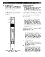
98.
AUX ST 1L, MON A L
AUX ST 1R, MON A R (meters and indicator)
These two meters normally monitor the corre-
spondingly labeled auxiliary 1 stereo (left and
right sides).
When the an input or bus CUE switch is engaged,
the meters display the Monitor A output signal
(which is the cue signal), and the MON indicator
above the meters turns on.
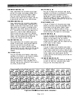
99. AUX ST 2 L, TB
AUX ST 2 R/OSC (meters and indicator)
These two meters normally monitor the corre-
spondingly labeled auxiliary 2 stereo (left and
right sides).
When the the talkback switch is engaged, the
AUX ST 2L meter instead displays the Talkback
output signal and the TB OSC indicator above
the meters turns on. When the oscillator output
is switched on, the AUX ST 2R meter instead
displays that oscillator signal, and again the TB
OSC indicator above the meters turns on.
100. MON meter function switch
If you wish to force the accompanying pair of
meters to indicate the monitor output levels when
no cue switch is engaged, press this switch. The
accompanying pair of meters will now display the
MON A left and right levels instead of the AUX
ST 1 levels.
Page 2-26
Summary of Contents for PM4000
Page 1: ...PROFESSIONAL AUDIO MIXING CONSOLE PM4000 OPERATING MANUAL YAMAHA ...
Page 2: ...PM4000 OPERATING MANUAL ...
Page 7: ...Section 1 Introduction ...
Page 11: ...Section 2 Brief Operating Instruction ...
Page 47: ...Section 3 Specifications ...
Page 51: ...Dimensional Drawings PM4000 Console all versions Page 3 4 ...
Page 52: ...Page 3 5 ...
Page 53: ...Page 3 6 PM4000 Console Rear Profiles ...
Page 54: ...Module Block Diagrams See back of the manual for overall system block diagram Page 3 7 ...
Page 55: ...Page 3 8 ...
Page 56: ...Page 3 9 ...
Page 57: ...Page 3 10 ...
Page 58: ...Page 3 11 ...
Page 59: ...Page 3 12 ...
Page 60: ...Section 4 Installation Notes ...
Page 72: ...Figure 4 13 Cables For Use With Balanced Sources Page 4 12 ...
Page 79: ...SECTION 5 Gain Structure and Levels ...
Page 82: ...Figure 5 1 Dynamic Range and Headroom in Sound Systems Page 5 3 ...
Page 86: ...Section 6 Optional Functions ...
Page 106: ...Section 7 Operating Notes and Hints ...
Page 119: ...Section 8 Applications ...
Page 127: ...Section 9 Maintenance ...
Page 131: ......
Page 132: ...YAMAHA VN02300 ...


