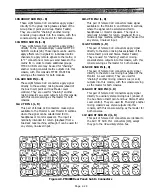
122. AUX INSERT 1-8 (IN, OUT)
These phone jacks serve as a patch point for the
signal from the correspondingly numbered
auxiliary mixing bus. They function identically to
the insert points for the group mixing bus [118].
123. AUX ST INSERT 1 L & R (IN, OUT)
These four phone jacks serve as a patch point for
the signal from the left and right sides of the
number 1 auxiliary stereo mixing bus. They
function just like the Group Insert jacks [118],
except they affect the auxiliary 1 stereo output
instead of the group output.
124. AUX ST INSERT 2 L & R (IN, OUT)
These phone jacks are just like the AUX ST
INSERT 1 L & R jacks [123], except the affect the
number 2 auxiliary stereo mixing bus.
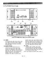
125. VCA: SLAVE/OFF/MASTER (1-4, 5-8)
This pair of rotary, screwdriver-operated switches
determine whether this console or a remote
console’s master faders control this console’s
voltage-controlled amplifiers (VCAs). The function
may be switched separately for Masters 1 through
4 and 5 through 8.
When set to the MASTER, this console’s MASTER
FADERS [47] are in control of any other PM4000
connected to the VCA/MUTE CONTROL connector
[129].
SLAVE position disables this console’s VCA
126. MUTE: SLAVE/OFF/MASTER (1-4, 5-8)
& CUE/SOLO On/Off MASTER
The pair of rotary, screwdriver-operated switches
labeled MUTE determine whether this console or a
remote console’s master mute switches control this
console’s channel on/off mute groups. The function
may be switched separately for Master Mute
groups 1 through 4 and 5 through 8. The CUE/
SOLO switch determines whether the remote
console’s cue logic links to this console.
The rationale for splitting MUTE control between
groups 1 through 4 and 5 through 8 is the same as
that for the VCAs [125]. Control is applied via the
same multipin remote connector as the VCAs [129].
127. PHANTOM MASTER (+48V)
This recessed slide switch turns the console’s 48-
volt phantom power supply on and off. When this is
OFF, no power will be supplied to any mic,
regardless of the channel’s +48 V on/off switch
setting [4].
128. FAN (speed switch)
This switch sets the operating speed of the rear-
panel mounted cooling fans [107]. LOW position is
adequate for most operation. However, in high
ambient temperatures or where the console is
being used out-of-doors in direct sunlight, be sure
to use the HIGH position. Any time you feel the
front panel of the console becoming hotter than
usual, switch to HIGH position.
MASTER FADERS and,
instead, allows a second
PM4000, a PM3000, or a
specially designed remote
automation system to control
this console’s VCAs via the
VCA/MUTE CONTROL
connector [129].
When set to OFF, the remote
VCA function is disabled
altogether, and the
master faders are
effective and affected by
only this console.
Splitting control of
Masters 1-4 and 5-8
between two consoles
facilitates control of
complex mixing systems
by multiple console
operators.
129. VCA/MUTE
CONTROL
This multi-pin locking connector
is an input/output point for
control voltages in the PM4000.
It enables two PM4000s to be
interlinked so that the muting
logic and VCA MASTER
S
from
one console also affect the
other. The adjacent VCA and
MUTE SLAVE/MASTER
switches [125], [126] affect the
function of this connector. This
connector also may be used for
interface to a remote control
system which may be
developed for “automation” of
master muting and group
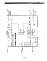
levels. Refer to Figure 2-13 for
details on wiring.
Figure 2-12. PM4000 Rear Panel: VCA/Mute Control Connector and Master Mode Switches
Page 2-31
Summary of Contents for PM4000
Page 1: ...PROFESSIONAL AUDIO MIXING CONSOLE PM4000 OPERATING MANUAL YAMAHA ...
Page 2: ...PM4000 OPERATING MANUAL ...
Page 7: ...Section 1 Introduction ...
Page 11: ...Section 2 Brief Operating Instruction ...
Page 47: ...Section 3 Specifications ...
Page 51: ...Dimensional Drawings PM4000 Console all versions Page 3 4 ...
Page 52: ...Page 3 5 ...
Page 53: ...Page 3 6 PM4000 Console Rear Profiles ...
Page 54: ...Module Block Diagrams See back of the manual for overall system block diagram Page 3 7 ...
Page 55: ...Page 3 8 ...
Page 56: ...Page 3 9 ...
Page 57: ...Page 3 10 ...
Page 58: ...Page 3 11 ...
Page 59: ...Page 3 12 ...
Page 60: ...Section 4 Installation Notes ...
Page 72: ...Figure 4 13 Cables For Use With Balanced Sources Page 4 12 ...
Page 79: ...SECTION 5 Gain Structure and Levels ...
Page 82: ...Figure 5 1 Dynamic Range and Headroom in Sound Systems Page 5 3 ...
Page 86: ...Section 6 Optional Functions ...
Page 106: ...Section 7 Operating Notes and Hints ...
Page 119: ...Section 8 Applications ...
Page 127: ...Section 9 Maintenance ...
Page 131: ......
Page 132: ...YAMAHA VN02300 ...


