2.4 The PW4000 Power Supply
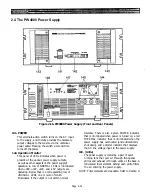
Figure 2-16. PW4000 Power Supply (Front and Rear Panels)
141. POWER
This alternate-action switch turns on the AC input
to the supply, and thereby provides the necessary
output voltages to the console via the umbilical
power cable. Pressing the switch a second time
turns off the power.
142. Operation Monitor
This panel of LEDs indicates when power is
present at the various power supply outputs,
as well as other aspects of the power supply’s
operation. A row of NORMAL LEDs is illuminated
when +48V, +12V, +19V, and -19V outputs are
operating. Below that is a corresponding row of
UNUSUAL LEDs, one or more of which
illuminates if the output is not within normal
tolerance. There is also a green POWER indicator
that is illuminated when power is turned on, a red
THERMAL indicator that is illuminated when the
power supply has overheated (and automatically
shut down), and a digital indicator that displays
the AC line voltage input to the power supply.
143. (Grille)
The power supply is cooled by a pair of quiet
running fans that pull air through front-panel
grilles and exhaust it through vents at the back. A
reticulated foam element behind each grille filters
the air entering the power supply.
NOTE: Filter elements are cleanable. Refer to Section 9.
Page 2-34
Summary of Contents for PM4000
Page 1: ...PROFESSIONAL AUDIO MIXING CONSOLE PM4000 OPERATING MANUAL YAMAHA ...
Page 2: ...PM4000 OPERATING MANUAL ...
Page 7: ...Section 1 Introduction ...
Page 11: ...Section 2 Brief Operating Instruction ...
Page 47: ...Section 3 Specifications ...
Page 51: ...Dimensional Drawings PM4000 Console all versions Page 3 4 ...
Page 52: ...Page 3 5 ...
Page 53: ...Page 3 6 PM4000 Console Rear Profiles ...
Page 54: ...Module Block Diagrams See back of the manual for overall system block diagram Page 3 7 ...
Page 55: ...Page 3 8 ...
Page 56: ...Page 3 9 ...
Page 57: ...Page 3 10 ...
Page 58: ...Page 3 11 ...
Page 59: ...Page 3 12 ...
Page 60: ...Section 4 Installation Notes ...
Page 72: ...Figure 4 13 Cables For Use With Balanced Sources Page 4 12 ...
Page 79: ...SECTION 5 Gain Structure and Levels ...
Page 82: ...Figure 5 1 Dynamic Range and Headroom in Sound Systems Page 5 3 ...
Page 86: ...Section 6 Optional Functions ...
Page 106: ...Section 7 Operating Notes and Hints ...
Page 119: ...Section 8 Applications ...
Page 127: ...Section 9 Maintenance ...
Page 131: ......
Page 132: ...YAMAHA VN02300 ...


