Section 4.
Installation Notes
4.1 Planning An Installation
Before installing the PM4000, it is worthwhile
considering how it will be used, how it is going to be
connected, and what is the best way to implement the
installation.
To begin with, there must be a surface upon which
the console can be mounted. A desk or table top can be
constructed to support the console. It should be capable
of supporting at least the weight of the console plus a
human console operator leaning on the arm rest; the
sturdier, the better. There should be adequate access
behind the console to allow for cable connections and
“service loops” of extra cable so that the console can be
moved without disconnecting everything. The dimen-
sions listed in the SPECIFICATIONS section of this
manual can be given to the carpenter or other personnel
responsible for building the console support.
Be sure to provide a location within 10 feet (3.5
meters) of the console for housing the PW4000 power
supply. This supply may be rack mounted, or it may be
placed on a shelf. For touring or critical fixed applica-
tions, it may be advisable to purchase a spare PW4000
supply and to mount it next to the main supply; auto-
matic changeover is then possible in the rare event of a
problem.
Experienced sound system installers will prepare a
detailed block diagram of the entire sound system prior
to installation. They will figure out all the necessary
cables, where they run, and the required length so that
the cables can be prepared ahead of time. In fixed
installations, this will enable appropriate conduit to be
installed (be sure to allow some extra “breathing room”
in the conduit to allow for cable replacement or future
additions. For open-air installations, such as outdoor
amphitheatres, there is no substitute for waterproof
conduit (it excludes moisture in the event of rain or
when the venue is washed down, thereby preventing
deterioration and short circuit of audio and power
cables).
4.2 Power Mains
4.2.1 Verify The Correct Mains Voltage
PW4000 power supplies sold in the U.S.A. and
Canada are designed to operate with 110 to 120 volt, 50
or 60 Hz AC power mains. The General Export model
operates on 220 to 230 volt, 50 or 60 Hz AC mains. The
British model operates on 240V AC mains. If you are
traveling with this equipment, be sure to test the power
mains, and to use the appropriate power supply. Con-
sult your Yamaha PM4000 dealer for assistance.
4.2.2 Ensure There is a Good Earth
Ground
The console must be grounded for safety and proper
shielding. A 3-wire power cable is provided for this
purpose. Use a special circuit tester to insure that the
outlet is properly grounded, and that the “neutral” is
not weak or floating. If a grounded, 3-wire outlet is not
available, or if there is any chance the outlet may not be
properly grounded, a separate jumper wire must be
connected from the console chassis to an earth ground.
In the past, cold water pipes often were relied upon
for an earth ground, although this is no longer the case
in many localities. Modern building codes often specify
that the water meter be isolated from the water mains
by a length of plastic (PVC) pipe; this protects water
company personnel working on the water mains from
being shocked. It also insulates the cold water pipes
from the earth ground. While an electrical wire by-
passes the water meter in some locations, this ground
path should not be assumed. For similar reasons, avoid
hot water pipes. Gas pipes should not be used because if
there is a poor electrical connection between two
sections of pipe, and if a ground current is being dissi-
pated through the pipe, there exists the potential for a
heat or spark-generated fire or explosion. The safest
and most reliable approach is to provide your own
ground. Drive at least 5 feet (1.5m) of copper pipe into
moist, salted earth, and use that for a ground, or use
one of the specially made chemical-type ground rods
available for this purpose.
CAUTION: Connect the PW4000 power
supply to the power mains only after
confirming that the voltage and line fre-
quency are correct. At the least, use a
Page 4-1
Summary of Contents for PM4000
Page 1: ...PROFESSIONAL AUDIO MIXING CONSOLE PM4000 OPERATING MANUAL YAMAHA ...
Page 2: ...PM4000 OPERATING MANUAL ...
Page 7: ...Section 1 Introduction ...
Page 11: ...Section 2 Brief Operating Instruction ...
Page 47: ...Section 3 Specifications ...
Page 51: ...Dimensional Drawings PM4000 Console all versions Page 3 4 ...
Page 52: ...Page 3 5 ...
Page 53: ...Page 3 6 PM4000 Console Rear Profiles ...
Page 54: ...Module Block Diagrams See back of the manual for overall system block diagram Page 3 7 ...
Page 55: ...Page 3 8 ...
Page 56: ...Page 3 9 ...
Page 57: ...Page 3 10 ...
Page 58: ...Page 3 11 ...
Page 59: ...Page 3 12 ...
Page 60: ...Section 4 Installation Notes ...
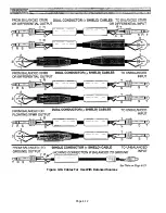
Page 72: ...Figure 4 13 Cables For Use With Balanced Sources Page 4 12 ...
Page 79: ...SECTION 5 Gain Structure and Levels ...
Page 82: ...Figure 5 1 Dynamic Range and Headroom in Sound Systems Page 5 3 ...
Page 86: ...Section 6 Optional Functions ...
Page 106: ...Section 7 Operating Notes and Hints ...
Page 119: ...Section 8 Applications ...
Page 127: ...Section 9 Maintenance ...
Page 131: ......
Page 132: ...YAMAHA VN02300 ...


