4.3 Theory of Grouding
Grounding is an area of “black magic” for many
sound technicians and engineers, and certainly for most
casual users of sound systems. Everyone knows that
grounding has something to do with safety, and some-
thing to do with hum and noise suppression, but few
people know how to set up a proper AC power distribu-
tion system, and how to connect audio equipment
grounds so that noise is minimized. This subsection of
the manual won’t make anyone an expert, but it does
point out a few of the principles and precautions with
which everyone should be familiar. Whether you read
this material or not, before you start cutting shields and
lifting grounds, read this warning:
WARNING: In any audio system installa-
tion, governmental and insurance under-
writers’ electrical codes must be observed.
These codes are based on safety, and may,
vary in different localities; in all cases,
local codes take precedence over any
suggestions contained in this manual.
Yamaha shall not be liable for incidental
or consequential damages, including
injury to any persons or property, result-
ing from improper, unsafe or illegal instal-
lation of a Yamaha mixing console or of
any related equipment; neither shall
Yamaha be liable for any such damages
arising from defects or damage resulting
from accident, neglect, misuse, modifica-
tion, mistreatment, tampering or any act
of nature. (IN PLAIN WORDS... IF YOU
LIFT A GROUND, THE RESULTING
POTENTIAL FOR ELECTRICAL SHOCK
IS YOUR OWN RESPONSIBILITY!)
Never trust any potentially hazardous
system, such as an AC power system of
any type, just because someone else tells
you that it’s okay. People can get killed by
faulty or improperly wired sound equip-
ment, so be sure you check things out
yourself.
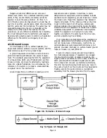
Ground is the electrical reference against which
potentials (voltages) are expressed. In a practical audio
system, a number of different independent references
exist in various local subsystems. These may or may not
be at the same electrical potential. If handled properly,
they certainly need not be at the same potential.
For purposes of clarity in discussing audio connec-
tion practices, we will distinguish among three specific
ground references:
•
Signal Ground
—
the reference point against
which signal potentials in a specific piece of equip-
ment or group of components are expressed.
•
Earth Ground
—
the local electrical potential of’
the earth. In practice, earth is the potential of the
central, rounded terminal in a U.S. standard three-
prong 120-volt outlet. Earth is sometimes obtained
from a metal cold water-pipe (though this practice
has been criticized recently as unreliable due to
increasing use of non-conductive ABS plastic pipe
sections), or from a chemical earthing rod sunk into
the moistened ground.
•
Chassis Ground
—
the chassis connection point of
a specific component. In equipment fitted with a
three prong AC plug, the chassis is normally
connected to earth, with provision to connect signal
ground to earth as well. Equipment having a two
prong AC plug will normally have the chassis
connected to signal ground.
As we will see, connections among these various
reference points are an all-important factor in assem-
bling a successful audio system.
4.3.1 Why Is Proper Grounding
Important?
In practical operating environments, any signal
conductor is susceptible to induced currents from
several types of sources such as radio frequency (RF)
emissions, AC power lines, switching devices, motors
and the like. This is why audio signal cables are invari-
ably shielded. The function of the shield is to intercept
undesirable emissions. A major goal of grounding
technique is to keep unwanted signal currents that are
induced in the shield away from the signal conductor(s),
and drain them to ground as directly as possible.
Beyond minimizing noise and hum, an equally
important consideration in grounding is safety. The
connection between a chassis and earth is commonly
referred to as a safety ground – and with good reason.
Consider the possibility that a chassis might become
connected to the hot leg of the AC mains (120 volts RMS
AC) due to faulty wiring, an inadvertent short or
moisture condensation. Suddenly, that innocuous
looking box could be transformed into what engineers
gruesomely call a widow maker. Someone who is
touching a grounded guitar, mic stand, or other equip-
ment will complete the circuit when touching the now
electrically charged chassis, and receive the full brunt of
whatever power is available. If the chassis is connected
to earth, it will simply blow a fuse or circuit breaker.
Page 4-5
Summary of Contents for PM4000
Page 1: ...PROFESSIONAL AUDIO MIXING CONSOLE PM4000 OPERATING MANUAL YAMAHA ...
Page 2: ...PM4000 OPERATING MANUAL ...
Page 7: ...Section 1 Introduction ...
Page 11: ...Section 2 Brief Operating Instruction ...
Page 47: ...Section 3 Specifications ...
Page 51: ...Dimensional Drawings PM4000 Console all versions Page 3 4 ...
Page 52: ...Page 3 5 ...
Page 53: ...Page 3 6 PM4000 Console Rear Profiles ...
Page 54: ...Module Block Diagrams See back of the manual for overall system block diagram Page 3 7 ...
Page 55: ...Page 3 8 ...
Page 56: ...Page 3 9 ...
Page 57: ...Page 3 10 ...
Page 58: ...Page 3 11 ...
Page 59: ...Page 3 12 ...
Page 60: ...Section 4 Installation Notes ...
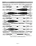
Page 72: ...Figure 4 13 Cables For Use With Balanced Sources Page 4 12 ...
Page 79: ...SECTION 5 Gain Structure and Levels ...
Page 82: ...Figure 5 1 Dynamic Range and Headroom in Sound Systems Page 5 3 ...
Page 86: ...Section 6 Optional Functions ...
Page 106: ...Section 7 Operating Notes and Hints ...
Page 119: ...Section 8 Applications ...
Page 127: ...Section 9 Maintenance ...
Page 131: ......
Page 132: ...YAMAHA VN02300 ...


