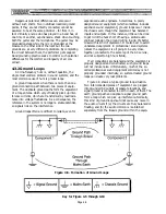
end without affecting the audio signal on the two inner
conductors of the cable, and with little or no effect on
the shielding. Unfortunately, this is not a very practical
solution to the ground loop problem for portable sound
systems because it requires special cables with shields
disconnected on one end. Fortunately, some professional
audio equipment, including Yamaha PC-Series amps, is
equipped with ground lift switches on the balanced
inputs.
CAUTION: Microphone cases typically are
connected to the shield of the cable, and
the shield is tied to the console chassis via
pin 1 of the XLR connector. If there is any
electrical potential on any external equip-
ment, such as a guitar amp chassis, then a
performer who holds the mic and touches
the other equipment may be subject to a
lethal electrical shock! This is why you
should avoid “ground lift” adaptors on AC
power connections if there is any other
way to eliminate a ground loop.
In those audio devices which anticipate ground loops
by providing “ground lift” switches next to XLRs or
three-wire phone jacks, the ground lift switch makes
and breaks the connection between the connector’s
shield and the chassis of the particular device. Ground
lift switches are usually found on “direct boxes”, which
are used when an electric musical instrument is to be
plugged directly into a console whose inputs are not
designed
to
accommodate direct connection of such
instruments (a direct box also includes a transformer
and/or isolation amplifier, as discussed in Section 4.5).
One of the best ways to exclude noise from a micro-
phone input is to use a high-quality, low-impedance
microphone and to connect it to the console’s low-
impedance, balanced (or “floating”) input. Use high-
quality microphone cables fitted with XLR connectors,
and keep microphone cables as short as possible. Also,
physically separate mic cables from line-level (console
output) cables, speaker cables and AC cables.
4.4 Audio Connectors and Cables
The signal-carrying cables in a sound system are as
much an audio "component" as any other part of the
system. Improper cables between the equipment can
result in exaggerated or deficient high frequency
response, degradation of signal-to-noise ratio, and other
problems. Use of the proper cables is essential if the full
potential of high quality sound equipment is to be
realized.
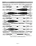
Figure 4-11a. T/R/S Phone Plug Wiring For
PM4000 Insert In/Out Jacks and Direct Out Jacks
Figure 4-11c. Female XLR Connector Wiring For
PM4000 3-pin XLR Outputs
Page 4-9
Summary of Contents for PM4000
Page 1: ...PROFESSIONAL AUDIO MIXING CONSOLE PM4000 OPERATING MANUAL YAMAHA ...
Page 2: ...PM4000 OPERATING MANUAL ...
Page 7: ...Section 1 Introduction ...
Page 11: ...Section 2 Brief Operating Instruction ...
Page 47: ...Section 3 Specifications ...
Page 51: ...Dimensional Drawings PM4000 Console all versions Page 3 4 ...
Page 52: ...Page 3 5 ...
Page 53: ...Page 3 6 PM4000 Console Rear Profiles ...
Page 54: ...Module Block Diagrams See back of the manual for overall system block diagram Page 3 7 ...
Page 55: ...Page 3 8 ...
Page 56: ...Page 3 9 ...
Page 57: ...Page 3 10 ...
Page 58: ...Page 3 11 ...
Page 59: ...Page 3 12 ...
Page 60: ...Section 4 Installation Notes ...
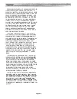
Page 72: ...Figure 4 13 Cables For Use With Balanced Sources Page 4 12 ...
Page 79: ...SECTION 5 Gain Structure and Levels ...
Page 82: ...Figure 5 1 Dynamic Range and Headroom in Sound Systems Page 5 3 ...
Page 86: ...Section 6 Optional Functions ...
Page 106: ...Section 7 Operating Notes and Hints ...
Page 119: ...Section 8 Applications ...
Page 127: ...Section 9 Maintenance ...
Page 131: ......
Page 132: ...YAMAHA VN02300 ...


