4.5.2 Active Guitar Direct Box
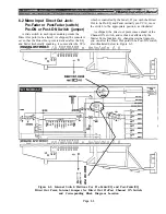
The active direct box shown here can be used at the
output of a standard electric guitar, with or without an
amplifier. Because of its very high input impedance, it
can be used with a piezoelectric instrument pickup,
taking the place of the preamp that is normally in-
cluded with such pickups. This box is not meant for use
at the output of a guitar amplifier (see PASSIVE
DIRECT BOX information). The active direct box can be
powered by its own pair of standard 9V “transistor
radio” type batteries, or by phantom power from the
PM4000 or any condenser microphone power supply.
The circuit can be constructed on a piece of perf
board, or on terminal strips, or on a printed circuit
layout. It should be assembled into a shielded case,
using isolated (insulated) phone jacks, as shown. When
the direct box is used between the guitar and guitar
amplifier, place the ground switch in the position that
yields the minimum hum. As with the passive direct
box, any part substitution should be carefully consid-
ered.
4.6 Configuring Equipment Racks
The great majority of audio equipment manufactur-
ers make provision for their electronic products to be
mounted in EIA standard 19 inch wide equipment
racks. (The equipment may be only 17 to 18 inches in
width, or even less. The rack ears that mount to the
rack rails extend to 19 inches.) Panel heights for rack
mounting equipment are standardized on multiples of a
single rack unit space (1 RU) of 1.75 inches.
When selecting electronic equipment it is important
to bear in mind eventual rack mounting. Not only the
height but also the depth of the unit should be consid-
ered. Particularly in portable applications, the integrity
and strength of the front panel and/or rack mounting
ears also must be examined in relation to the chassis
weight. Heavy components such as power amplifiers
should be supported at the rear as well, rather than
relying only on the front rack ears. Even if a piece of
equipment seems secure when you screw its front panel
to the rack rails, the vibration and shock encountered in
the back of a semi-trailer may quickly bend metal or
break it right out of the rack.
Figure 4-16. Active Musical Instrument Direct Box (D.I. Box) Schematic Diagram
Page 4-17
Summary of Contents for PM4000
Page 1: ...PROFESSIONAL AUDIO MIXING CONSOLE PM4000 OPERATING MANUAL YAMAHA ...
Page 2: ...PM4000 OPERATING MANUAL ...
Page 7: ...Section 1 Introduction ...
Page 11: ...Section 2 Brief Operating Instruction ...
Page 47: ...Section 3 Specifications ...
Page 51: ...Dimensional Drawings PM4000 Console all versions Page 3 4 ...
Page 52: ...Page 3 5 ...
Page 53: ...Page 3 6 PM4000 Console Rear Profiles ...
Page 54: ...Module Block Diagrams See back of the manual for overall system block diagram Page 3 7 ...
Page 55: ...Page 3 8 ...
Page 56: ...Page 3 9 ...
Page 57: ...Page 3 10 ...
Page 58: ...Page 3 11 ...
Page 59: ...Page 3 12 ...
Page 60: ...Section 4 Installation Notes ...
Page 72: ...Figure 4 13 Cables For Use With Balanced Sources Page 4 12 ...
Page 79: ...SECTION 5 Gain Structure and Levels ...
Page 82: ...Figure 5 1 Dynamic Range and Headroom in Sound Systems Page 5 3 ...
Page 86: ...Section 6 Optional Functions ...
Page 106: ...Section 7 Operating Notes and Hints ...
Page 119: ...Section 8 Applications ...
Page 127: ...Section 9 Maintenance ...
Page 131: ......
Page 132: ...YAMAHA VN02300 ...


