Section 6.
Optional Functions
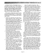
The PM4000 is factory wired to suit what Yamaha
engineers believe to be the greatest number of applica-
tions. Yamaha recognizes, however, that there are
certain functions which must be altered for certain
specific applications. In designing the PM4000, a
number of optional functions have been built in, and
can be selected by moving factory preset switches
within certain modules.
WARNING: Underwriter’s Laboratories
(UL) requires that we inform you there
are no user-serviceable parts inside the
PM4000. Only qualified service personnel
should attempt to open the meter bridge,
to remove a module, or to gain access to
the inside of the console or power supply
for any purpose. Lethal voltages are
present inside the power supply, and the
AC line cord and console umbilical cord
should be disconnected prior to opening
the console.
WARNING: We at Yamaha additionally
caution you never to open the console and
remove or install a module for the pur-
pose of inspection, replacement or chang-
ing the preset switches unless the power
has first been turned off. If a module is
removed or installed with power on, the
circuitry may be damaged. Unless you are
a qualified service technician, do not plug
in the AC cord while the interior of the
power supply is exposed; dangerous volt-
ages may exist within the chassis, and
lethal shock is possible. Yamaha neither
authorizes nor encourages unqualified
personnel to service modules or console
internal wiring. Damage to the console,
the individual, and other equipment in
the sound system can result from im-
proper service or alterations, and any
such work may void the warranty.
Page 6-1
Summary of Contents for PM4000
Page 1: ...PROFESSIONAL AUDIO MIXING CONSOLE PM4000 OPERATING MANUAL YAMAHA ...
Page 2: ...PM4000 OPERATING MANUAL ...
Page 7: ...Section 1 Introduction ...
Page 11: ...Section 2 Brief Operating Instruction ...
Page 47: ...Section 3 Specifications ...
Page 51: ...Dimensional Drawings PM4000 Console all versions Page 3 4 ...
Page 52: ...Page 3 5 ...
Page 53: ...Page 3 6 PM4000 Console Rear Profiles ...
Page 54: ...Module Block Diagrams See back of the manual for overall system block diagram Page 3 7 ...
Page 55: ...Page 3 8 ...
Page 56: ...Page 3 9 ...
Page 57: ...Page 3 10 ...
Page 58: ...Page 3 11 ...
Page 59: ...Page 3 12 ...
Page 60: ...Section 4 Installation Notes ...
Page 72: ...Figure 4 13 Cables For Use With Balanced Sources Page 4 12 ...
Page 79: ...SECTION 5 Gain Structure and Levels ...
Page 82: ...Figure 5 1 Dynamic Range and Headroom in Sound Systems Page 5 3 ...
Page 86: ...Section 6 Optional Functions ...
Page 106: ...Section 7 Operating Notes and Hints ...
Page 119: ...Section 8 Applications ...
Page 127: ...Section 9 Maintenance ...
Page 131: ......
Page 132: ...YAMAHA VN02300 ...


