6.1 Removing and Installing A Module
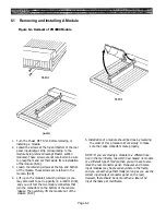
Figure 6-1. Removal of PM4000 Module
1. Turn the Power OFF first, before removing or
installing a module.
2. Loosen the screws at the top and bottom of the rear
panel input/output strip corresponding to the
module being removed (except Master section
modules). These screws are not retained so be sure
to grasp them and set them aside for reinstallation
of the module. [6-1A]
3. Loosen the retaining screws at the top and bottom
of the module. These screws are retained in the
module. [6-1B]
4. Lift up on the module’s retaining screws (or you
may also want to pull up gently on a control knob),
and you will feel the two module connectors that
join the connectors on the bottom of the console
release. Then carefully lift the module out of the
console. [6-1C]
5. Installation of a module should be done by reversing
the order of this procedure. Work slowly to make
sure that edge connectors mate properly.
NOTE: If you are moving a module to a different loca-
tion in the mainframe, one which had housed no module
or a different type of module, then you will have to also
move the rear connector panel. Monaural and Stereo
input modules may be placed anywhere in the frame,
and you can exchange them freely (so long as you use the
correct input/output connector panel on the rear).
However, there should be no more than a total of 64
input channels per mainframe.
Page 6-2
Summary of Contents for PM4000
Page 1: ...PROFESSIONAL AUDIO MIXING CONSOLE PM4000 OPERATING MANUAL YAMAHA ...
Page 2: ...PM4000 OPERATING MANUAL ...
Page 7: ...Section 1 Introduction ...
Page 11: ...Section 2 Brief Operating Instruction ...
Page 47: ...Section 3 Specifications ...
Page 51: ...Dimensional Drawings PM4000 Console all versions Page 3 4 ...
Page 52: ...Page 3 5 ...
Page 53: ...Page 3 6 PM4000 Console Rear Profiles ...
Page 54: ...Module Block Diagrams See back of the manual for overall system block diagram Page 3 7 ...
Page 55: ...Page 3 8 ...
Page 56: ...Page 3 9 ...
Page 57: ...Page 3 10 ...
Page 58: ...Page 3 11 ...
Page 59: ...Page 3 12 ...
Page 60: ...Section 4 Installation Notes ...
Page 72: ...Figure 4 13 Cables For Use With Balanced Sources Page 4 12 ...
Page 79: ...SECTION 5 Gain Structure and Levels ...
Page 82: ...Figure 5 1 Dynamic Range and Headroom in Sound Systems Page 5 3 ...
Page 86: ...Section 6 Optional Functions ...
Page 106: ...Section 7 Operating Notes and Hints ...
Page 119: ...Section 8 Applications ...
Page 127: ...Section 9 Maintenance ...
Page 131: ......
Page 132: ...YAMAHA VN02300 ...


