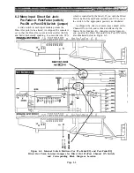
6.3 Mono Input Aux Sends: Pre Fader
& EQ or Pre Fader/post EQ
Ten slide switches in each input module permit each
of the eight mono auxiliary sends and the two stereo
aux sends to be altered. As shipped, the console is wired
so that if the front-panel aux PRE/OFF/POST switch is
set to PRE position, the aux send is derived ahead of the
the fader and equalizer (but after the high pass filter).
where the channel EQ for the house may not be desired
for the monitors, yet rumble-reducing filtering is
desirable. On the other hand, suppose that one aux mix
is used for a pre-fader effects send. In this case, it may
be desirable to apply channel EQ to the send. The POST
position would provide EQ, but would also cause the
channel fader to affect the send, which is not desirable.
To solve the problem, the switch for that aux send can
be reset so that the PRE position remains pre-fader, but
This is useful for stage monitor work, for example,
is taken after the EQ.
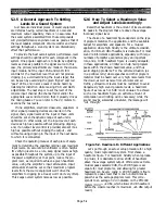
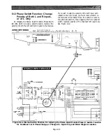
Figure 6-3. Internal Switch Positions for Mono Input Module Pre-EQ and Post-EQ Aux Send,
and Corresponding Block Diagram Locations:
Slide the Switches Toward Front Panel to Select Post-EQ, Toward Rear of Module for Pre-EQ.
Page 6-4
Summary of Contents for PM4000
Page 1: ...PROFESSIONAL AUDIO MIXING CONSOLE PM4000 OPERATING MANUAL YAMAHA ...
Page 2: ...PM4000 OPERATING MANUAL ...
Page 7: ...Section 1 Introduction ...
Page 11: ...Section 2 Brief Operating Instruction ...
Page 47: ...Section 3 Specifications ...
Page 51: ...Dimensional Drawings PM4000 Console all versions Page 3 4 ...
Page 52: ...Page 3 5 ...
Page 53: ...Page 3 6 PM4000 Console Rear Profiles ...
Page 54: ...Module Block Diagrams See back of the manual for overall system block diagram Page 3 7 ...
Page 55: ...Page 3 8 ...
Page 56: ...Page 3 9 ...
Page 57: ...Page 3 10 ...
Page 58: ...Page 3 11 ...
Page 59: ...Page 3 12 ...
Page 60: ...Section 4 Installation Notes ...
Page 72: ...Figure 4 13 Cables For Use With Balanced Sources Page 4 12 ...
Page 79: ...SECTION 5 Gain Structure and Levels ...
Page 82: ...Figure 5 1 Dynamic Range and Headroom in Sound Systems Page 5 3 ...
Page 86: ...Section 6 Optional Functions ...
Page 106: ...Section 7 Operating Notes and Hints ...
Page 119: ...Section 8 Applications ...
Page 127: ...Section 9 Maintenance ...
Page 131: ......
Page 132: ...YAMAHA VN02300 ...


