6.9 Stereo Input Channel Aux Sends
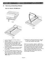
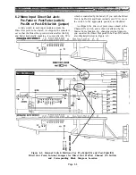
1-8: L+R Blend or Stereo Pairs
and right inputs to the channel. Moving the switch
changes the signal take-off points so that the odd-
numbered Aux Sends derive signal from the channel’s
A single slide switch in each stereo input module
left input path, and the even-numbered Aux Sends
changes the signal source for the Aux Sends 1 through 8
derive signal from the channel’s right input path. See
(without regard to pre or post status). As shipped, these
Figure 6-9.
Aux Sends each carry a mono combination of the left
Figure 6-9. Internal Switch Position For Stereo Input Module Aux Send 1-8 Mono Combine
or Stereo Paired Signal Sourcing, and Corresponding Location on Block Diagram.
Page 6-10
Summary of Contents for PM4000
Page 1: ...PROFESSIONAL AUDIO MIXING CONSOLE PM4000 OPERATING MANUAL YAMAHA ...
Page 2: ...PM4000 OPERATING MANUAL ...
Page 7: ...Section 1 Introduction ...
Page 11: ...Section 2 Brief Operating Instruction ...
Page 47: ...Section 3 Specifications ...
Page 51: ...Dimensional Drawings PM4000 Console all versions Page 3 4 ...
Page 52: ...Page 3 5 ...
Page 53: ...Page 3 6 PM4000 Console Rear Profiles ...
Page 54: ...Module Block Diagrams See back of the manual for overall system block diagram Page 3 7 ...
Page 55: ...Page 3 8 ...
Page 56: ...Page 3 9 ...
Page 57: ...Page 3 10 ...
Page 58: ...Page 3 11 ...
Page 59: ...Page 3 12 ...
Page 60: ...Section 4 Installation Notes ...
Page 72: ...Figure 4 13 Cables For Use With Balanced Sources Page 4 12 ...
Page 79: ...SECTION 5 Gain Structure and Levels ...
Page 82: ...Figure 5 1 Dynamic Range and Headroom in Sound Systems Page 5 3 ...
Page 86: ...Section 6 Optional Functions ...
Page 106: ...Section 7 Operating Notes and Hints ...
Page 119: ...Section 8 Applications ...
Page 127: ...Section 9 Maintenance ...
Page 131: ......
Page 132: ...YAMAHA VN02300 ...


