11
DGX-220/YPG-225
3.
TWL and TWR(PN 4/5, 5/5) Circuit
Boards, Speaker (Tweeter)
(Time required: About 4 minutes for
each)
3-1
Remove the lower case assembly. (See procedure
1.)
3-2
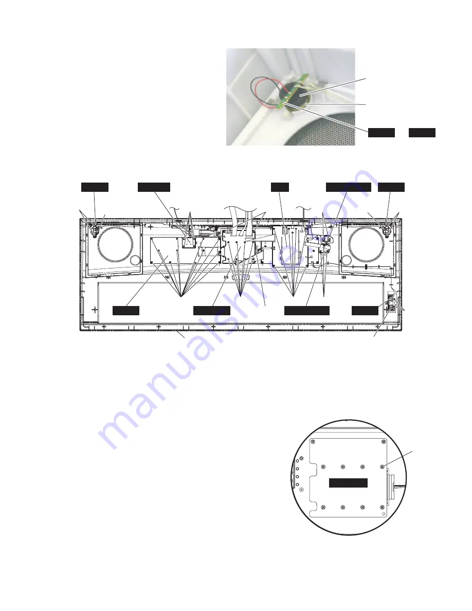
Remove two (2) screws marked [180A]. The
TWL(PN 4/5, 5/5) circuit board can then be
removed. (Fig.6)
3-3
Remove the speaker (tweeter). (Fig.5)
*
The TWR circuit board can be removed in the
same manner.
(Fig.5)
[180]: Bind Head Tapping Screw-B 3.0X8 MFZN2W3 (WE774300)
[380]: Bind Head Tapping Screw-B 3.0X12 MFZN2W3 (WE987400)
(Fig.7)
Sponge
Speaker (Tweeter)
TWR
TWL
or ( )
(Fig.6)
1 7 8 2
3 4 5 6
DMLCD
[380] x 8
4.
PB(AMJK 6/6) Circuit Board
(Time required: About 4 minutes)
4-1
Remove the lower case assembly. (See procedure 1.)
4-2
Remove two (2) screws marked [180B]. The PB (AMJK 6/6) circuit
board and the wheel assembly can then be removed. (Fig.6)
*
The wheel assembly is inserted and mounted on the volume shaft of the
PB (AMJK 6/6) circuit board.
5.
DMLCD Circuit Board, LCD Unit
(Time required: About 5 minutes)
5-1
Remove the lower case assembly. (See procedure 1.)
5-2
Remove two (2) screws marked [180C] and eight (8) screws marked
[380]. The DMLCD circuit board and LCD unit can then be removed.
(Fig.6)
*
When installing the DMLCD circuit board, tighten the screws from
No.1 through No.8 in order as shown in Fig.7.
[380]: Bind Head Tapping Screw-B 3.0X12 MFZN2W3 (WE987400)
[180A]
Speaker
(Tweeter(R))
Speaker
(Tweeter(R))
[180A]
[180B]
Wheel assembly
PB
Upper Case
(AMJK 6/6)
[380]
[180I]
[180F]
TWR
(PN 4/5,5/5)
TWL
(PN 4/5,5/5)
[180E]
AMJK 5/6
[180D]
PNR
(PN 1/5)
DMLCD
LCD unit
AMJK 4/6
(AMJK 1/6)
AM
[180C]
[180H]
PN 2/5


