background image

PSR-260/262

7

DISASSEMBLY PROCEDURE

1.

Bottom Case Assembly

1-1

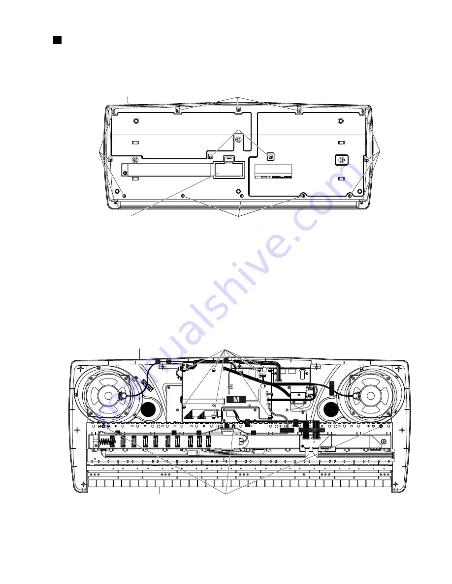
Remove the battery cover assembly. (Fig. 1)

Bottom Case Assembly

[230]

[230]

[230]

[230]

[240a]

Battery Cover

2.

M Circuit Board

2-1

Remove the bottom case assembly. (See procedure 1.)

2-2

Remove the eight (8) screws marked [220a]. Then
the M circuit board can then be removed. (Fig. 2)

Keyboard Assembly

Upper Case Assembly

[220a]

[240b]

[230]: Bind Head Tapping Screw-P 3.0 x 12 MFZN2Y (EP600300)

[240]: Bind Head Tapping Screw-P 3.0 x 25 MFZN2Y (VK228100)

1-2

Remove the fifteen (15) screws marked [230] and the
two (2) screws marked [240a]. The bottom case
assembly can then be removed. (Fig. 1)

3.

Keyboard Assembly

3-1

Remove the bottom case assembly. (See procedure 1.)

3-2

Remove the three (3) screws marked [240b]. Then
the keyboard can then be removed. (Fig. 2)

(Fig. 1)

(Fig. 2)

[220]: Bind Head Tapping Screw-P 3.0 x 8 MFZN2Y (EP600280)

[240]: Bind Head Tapping Screw-P 3.0 x 25 MFZN2Y (VK228100)

Summary of Contents for PortaTone PSR-260

Page 1: ...LY PROCEDURE 7 CIRCUIT BOARDS 10 LSI PIN DISCRIPTION 14 IC BLOCK DIAGRAM 14 TEST PROGRAM INITIALIZE 15 MIDI IMPLEMENTATION CHART 17 PARTS LIST OVERALL CIRCUIT DIAGRAM HAMAMATSU JAPAN 1 43K 317 I T Printed in Japan 2000 05 PK 001638 PSR 260 PSR 262 This document is printed on chlorine free ECF paper with soy ink ...

Page 2: ...nges in specification are subject to change without notice or obligation to retrofit Should any discrepancy appear to exist please contact the distributor s Service Division WARNING Static discharges can destroy expencive components Discharge any static electricity your body may have accumulated by grounding yourself to the ground buss in the unit heavy gauge black wires connect to this buss IMPOR...

Page 3: ...etronome Volume Style controls Acmp On Off Sync Start Start Stop Intro Ending Main A B Auto Fill Song controls Start Stop Pause A B Repeat Fast Forward Rewind Melody Voice Change One Touch Setting 1 style 1 song Multi Pads 4 pads x 10 banks Yamaha Education Suite Dictionary Lesson 1 4 Preset songs 100 songs Amplifier 2 0W 2 0W MIDI IN OUT Auxiliary jacks PHONES OUTPUT DC IN 10 12V MIDI IN OUT SUST...

Page 4: ...button 7 DEMO button 8 Piano button 9 METRONOME button 10 DJ button 22 PHONES OUTPUT jack 23 DC IN 10 12V jack 11 Numeric keypad buttons 12 ACCONPANIMENT ON OFF button 13 SYNC START button 14 START STOP button 15 INTRO ENDING button 16 MAIN AUTO FILL button 17 TEMPO TAP button 18 SONG button 18 STYLE button 20 VOICE button 21 MULTI PAD buttons 24 MIDI IN OUT terminals 25 SUSTAIN jack Control Panel...

Page 5: ...623340 5 M CN302 M CN301 MIDI 7P L 370 V537940 6 LCD CN402 M CN401 LCD 9P L 270 V546610 7 LCD M GND L 200 V546920 8 M CN501 SPEAKER Lch SPL L 350 V538250 9 M CN502 SPEAKER Rch SPR L 400 V538270 10 PN CN602 M CN601 VR 5P L 280 V562650 11 M CN801 MKC CN2 MK1 11P L 470 V545340 12 M CN901 MKC CN1 MK2 13P L 540 V545350 13 MK H MK L MK B 12P L 220 VV58360 14 MKC CN3 MK L MK C 7P L 260 VV58350 15 MKC CN4...

Page 6: ... DRIVER MKSC 14MHz POWER AMP BA5417 IC501 IC101 IC102 REGULATOR 5V IC802 16P DECODER LVC138 IC801 16P DECODER LVC138 MIDI OUT MIDI IN SUSTAIN IC703 1 4 13 15 1 4 13 15 2 7 28 30 33 81 88 90 97 55 57 59 64 66 71 73 77 A0 A19 D0 D15 22 27 35 40 5 7 3 4 8 2 49 50 53 44 47 9 20 99 100 1 4 1 2 11 12 3 5 3 CN801 CN2 CN901 CN1 CN402 CN401 CN302 CN301 CN202 CN201 CN104 CN102 CN101 CN103 CN602 CN601 CN501 ...

Page 7: ...per Case Assembly 220a 240b 230 Bind Head Tapping Screw P 3 0 x 12 MFZN2Y EP600300 240 Bind Head Tapping Screw P 3 0 x 25 MFZN2Y VK228100 1 2 Remove the fifteen 15 screws marked 230 and the two 2 screws marked 240a The bottom case assembly can then be removed Fig 1 3 Keyboard Assembly 3 1 Remove the bottom case assembly See procedure 1 3 2 Remove the three 3 screws marked 240b Then the keyboard ca...

Page 8: ... knob on the con trol panel Fig 4 6 2 Remove the bottom case assembly See procedure 1 6 3 Remove the M circuit board See procedure 2 6 4 Remove the three 3 screws marked 220d Then the VR circuit board can then be removed Fig 3 7 PW Circuit Board 7 1 Remove the bottom case assembly See procedure 1 7 2 Remove the M circuit board See procedure 2 7 3 Remove the two 2 screws marked 220e Then the PW cir...

Page 9: ...le pressing the fifteen 15 hooks A inward and then remove the rubber contact Fig 7 Keyboard Assembly 220g 10 4 Remove the twenty one 21 screws marked 140 then remove the black keys from the lower register Afterward remove the white keys DFA and C and then remove the white keys CEFB from the higher register At this time lift the keys from the front and slide them towards you The keys can then be re...

Page 10: ...Component side Note See partslist for details of circuit board component parts DC IN PHONES OUTPUT to LCD Unit to BATTERY to SW CN102 to SPEAKER L to SPEAKER R to VR CN602 to MIDI CN301 to MKC CN1 to MKC CN2 to PN CN202 to LCD CN402 M 2NA V536720 1 ...

Page 11: ...PSR 260 262 11 Pattern side ...

Page 12: ... 3 MULTI PAD 2 MULTI PAD 1 VOICE STYLE SONG TEMPO TAP MAIN A B INTRO ENDING STYLE START STOP SYNC START L TOUCH R OVERALL DICT ACOMPA ON OFF SUSTAIN IN to M CN301 PN Circuit Board MIDI Circuit Board MIDI 2NA V536720 1 PN 2NA V536700 Note See partslist for details of circuit board component parts Boxed names on the Circuit Board are switch name ...

Page 13: ...Note See partslist for details of circuit board component parts LCD Circuit Board MKC Circuit Board VR Circuit Board PW Circuit Board to MK H to MK L to MK L to M CN901 to M CN801 to M CN601 to M CN101 to M CN401 PN 2NA V536700 LCD 2NA V536370 MKC 2NA V345820 VR 2NA V536700 PW 2NA V536700 ...

Page 14: ...utput 99 MIDII I MIDI Input 50 X_I I Crystal quarts Input 100 MIDIO O MIDI Output PSR 260 262 14 YMW728 F XU355A00 GEW12 AWM Tone Generator LSI PIN DISCRIPTION M IC701 IC BLOCK DIAGRAM PIN NAME I O FUNCTION PIN NAME I O FUNCTION NO NO 1 S22 O 41 DB2 I O 2 S21 O 42 DB3 I O 3 S20 O 43 DB4 I O Data interface 4 S19 O 44 DB5 I O 5 S18 O 45 DB6 I O 6 S17 O 46 DB7 I O 7 S16 O 47 C1 O 8 S15 O 48 C2 O 9 S1...

Page 15: ...hk 1 Checks all the RAMs which are connected to the CPU The test result appears on the LCD 11 011 TG1 Chk Outputs the sine wave by changing the channels in sequence from C2 to D 3 After auto scaling is finished individual keys can be played If playing two or more keys simultaneously the first pressed key has priority to make a sound 13 013 Pit Chk Connect the frequency counter to the PHONES AUX OU...

Page 16: ...hat the C4 note is output when pushing the pedal and that the tone is turned off when releasing the pedal The test result appears on the LCD 37 037 MIDI Chk After connecting the MIDI IN jack and MIDI OUT jack with a MIDI cable execute the test Check that the C4 note is output and that the test result appears on the LCD If the test result is NG press the lowest leftmost key on the keyboard to execu...

Page 17: ...Exclusive o 4 o 4 Song Pos x x Common Song Sel x x Tune x x System Clock x x Real Time Commands x x Aux All Sound OFF x x Reset All Cntrls x x Local ON OFF x x All Notes OFF x x Mes Active Sense o o sages Reset x x Mode 1 OMNI ON POLY Mode 2 OMNI ON MONO o Yes Mode 3 OMNI OFF POLY Mode 4 OMNI OFF MONO x No NOTE 1 Depending on the selected voice the transmitted velocity value may differ even for no...

Page 18: ...Japanese model Y Export model CONTENTS OVERALL ASSEMBLY 2 KEYBOARD ASSEMBLY 4 ELECTRICAL PARTS 6 Note DESTINATION ABBREVIATIONS The numbers in QTY shows quantities for each unit The parts with in Part No are not available as spare parts The second letter of the shaded part number is I not one The second letter of the shaded part number is O not zero This mark in the REMARKS column means these part...

Page 19: ...2 PSR 260 OVERALL ASSEMBLY ...

Page 20: ...ly LCD Panel LCD Rubber Connector Rubber Connector Bind Head Tapping Screw P Circuit Board Connector Assembly Adhesive Tape 12 0cm 4ohm 3W A1 A2 A3 B C D E F G H PT 16M C61 P2M CH 3 0X8 MFZN2Y BL T1 6 KB200 3 0X8 MFZN2Y 3 0X12 MFZN2Y 3 0X25 MFZN2Y 4 0X8 MFZN2BL 12X90 12X50 18X25 PN M 2P L 250 650 11P L 470 MK1 13P L 540 MK2 PA 3B JP PA 32 CH TYPE A TYPE H SS 105L PO SS 105L 3 0X8 MFZN2Y LCD 2P L 2...

Page 21: ...4 PSR 260 KEYBOARD ASSEMBLY ...

Page 22: ...LY Keyboard Assembly Bind Head Tapping Screw P Bind Head Tapping Screw P Frame Frame White Key White Key White Key Black Key Felt Rubber Sheet Rubber Contact Rubber Contact Bind Head Tapping Screw P Bind Head Tapping Screw P Bind Head Tapping Screw P Grease Circuit Board Assembly Circuit Board Circuit Board Circuit Board Cable Cable Cable Cable Sponge Sponge Adhesive Tape Adhesive Tape 16M C61 P2M...

Page 23: ...tive Cera Cap Electrolytic Cap Semiconductive Cera Cap Semiconductive Cera Cap Electrolytic Cap Semiconductive Cera Cap Semiconductive Cera Cap Electrolytic Cap Semiconductive Cera Cap Semiconductive Cera Cap Ceramic Capacitor F Electrolytic Cap Semiconductive Cera Cap Semiconductive Cera Cap Semiconductive Cera Cap Electrolytic Cap Electrolytic Cap Electrolytic Cap Electrolytic Cap Electrolytic C...

Page 24: ...ve Cera Cap Semiconductive Cera Cap Electrolytic Cap Semiconductive Cera Cap Semiconductive Cera Cap Semiconductive Cera Cap Semiconductive Cera Cap Semiconductive Cera Cap Electrolytic Cap Ceramic Capacitor Array Ceramic Capacitor Array Ceramic Capacitor Array Ceramic Capacitor Array Wire Trap Base Post Connector Wire Trap Wire Trap Wire Trap Cable Holder Wire Trap Cable Holder Cable Holder Wire ...

Page 25: ... Resistor Carbon Resistor Carbon Resistor Carbon Resistor Carbon Resistor Carbon Resistor Carbon Resistor Carbon Resistor Carbon Resistor Carbon Resistor Carbon Resistor Carbon Resistor Carbon Resistor Carbon Resistor Carbon Resistor Metal Oxide Film Resistor Metal Oxide Film Resistor Carbon Resistor Carbon Resistor Carbon Resistor Carbon Resistor Carbon Resistor Carbon Resistor Carbon Resistor Ca...

Page 26: ...rap Wire Trap Wire Trap Circuit Board Cable Holder Cable Holder Cable Holder Push Switch Rotary Variable Resistor Connector Assembly Connector Assembly Connector Assembly Speaker Terminal Spring Terminal LCD Back Light Assembly Rubber Connector Rubber Connector Rubber Contact Rubber Contact AC Adapter AC Adapter 52147 12P TE 52147 7P TE MK H 1N4148 DO 34 52147 12P TE 52147 5P TE 16M MKC 10X64X0 5 ...

Page 27: ... M 28CC1 8816209 MKC 28CC1 8816209 MK 28CC1 8816209 MIDI 28CC1 8816209 PN 28CC1 8816209 SW 28CC1 8816209 VR 28CC1 8816209 LCD 28CC1 8816209 WARNING Components having special characteristics are marked and must be replaced with parts having specification equal to those originally installed Note See parts list for details of circuit board component parts RE5RE33AA XW964A00 REGULATOR 3 3V 1 GND 2 V i...

Reviews: