1
2
3
4
5
6
7
8
A
B
C
D
E
F
G
H
I
J
K
L
■
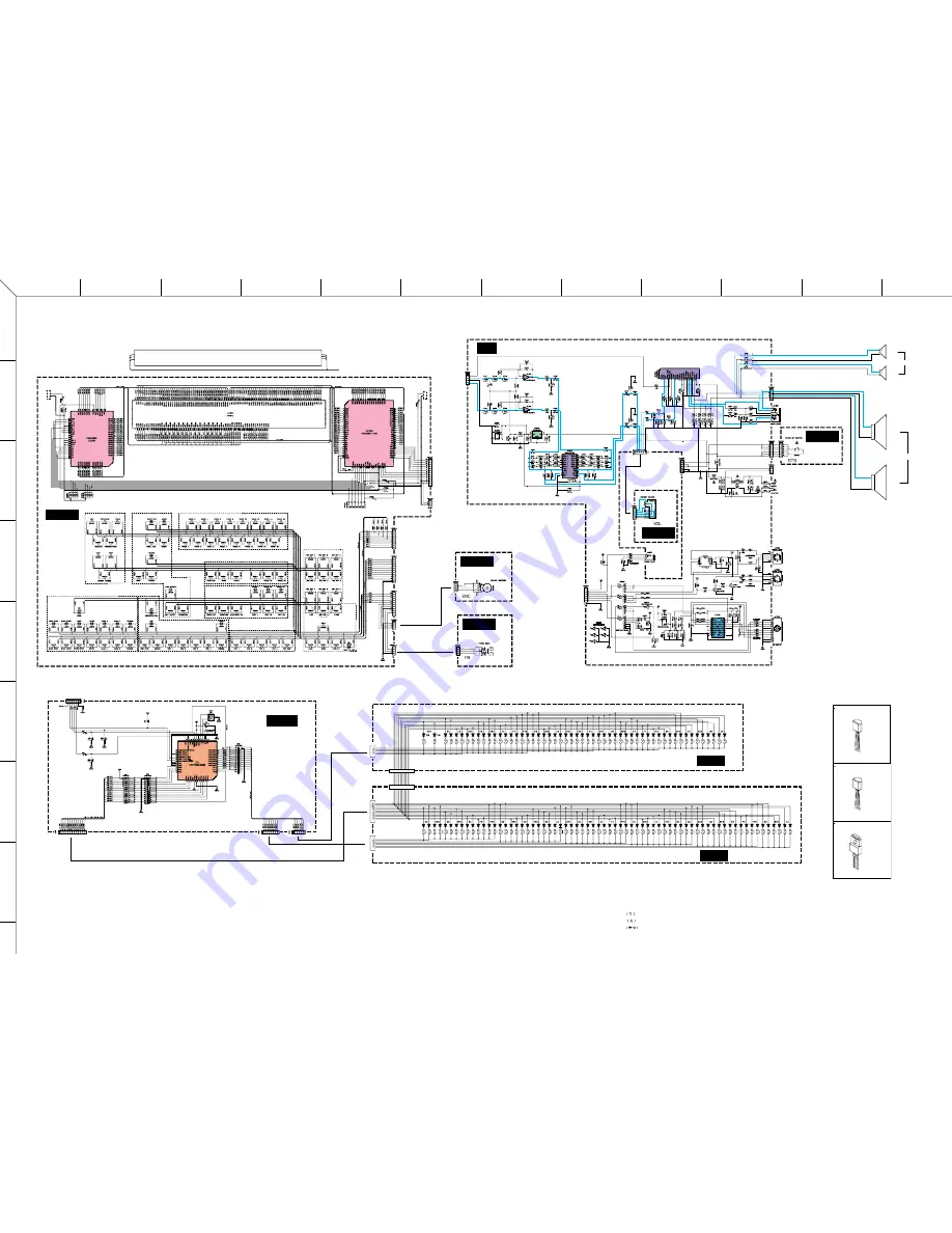
PSR-550 OVERALL CIRCUIT DIAGRAM 2/2 (PN, AM, MKS5, MK-L, MK-H)
L
R
L
R
WOOFER
TWEETER
to DM-CN550
to DM-CN150
to DM-CN650
to DM-CN180
to DM-CN920
to
DM-CN250
to
DM-CN750
to
DM-CN960
PHONES/OUTPUT
to BATTERY
DC IN 10-12V
MIDI IN
MIDI OUT
TO HOST
PN 1/5
PN 2/5
PN 3/5
PN 4/5
PN 5/5
MK-H
MK-L
MKS5
to DM-CN170
FOOT
SWITCH
MASTER
VOLUME
STANDBY/ON
HOST SELECT
Data dial
PITCH BEND
AM
LCD BACK LIGHT
LCD
to DM-CN999
not installed
not installed
+
–
+
–
LCD DRIVER
LCD DRIVER
HPF
EQUALIZER
AMP
POWER AMP
PHOTO CAUPLER
HOST I/F
LINE TRANSCEIVE
INVERTER
REGULATOR
+6V
CPU
PN:
28CC1-8819394
AM:
28CC1-8813690
MK-H: 28CC1-8812655
MK-L: 28CC1-8812655
REG6V
AN78L06 (XE924A00)
2
1
3
3: OUTPUT
2: GND
1: INPUT
REG5V
S81250SGY-Z (XT625A00)
2
1
3
3: OUTPUT
2: INPUT
1: GND
REG3.3V
µ
PC29M33HF (XT333A00)
1
2
3
3: OUTPUT
2: COMMON
1: INPUT
:
Mylar Capacitor
:
Ceramic Capacitor
: Semiconductive Ceramic Capacitor
Note : See parts list for details of circuit board component parts.
WARNING
Components having special characteristics are marked
Z
and must be replaced with parts having speci-
fication equal to those originally installed.


