PSR-740/PSR-640
[140]
[140]
15.
FDD
15-1
Remove the lower case assembly. (See procedure 1.)
15-2
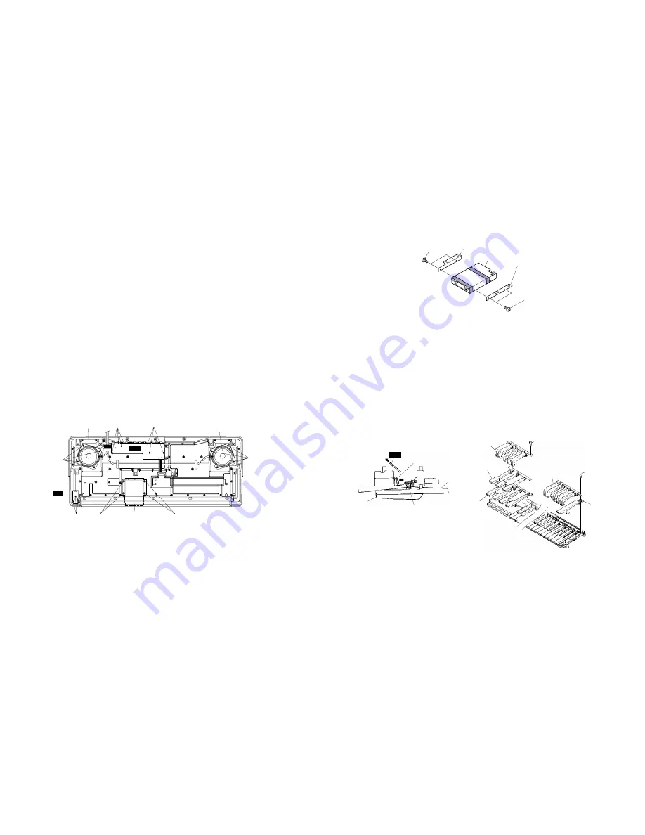
Remove the four (4) screws marked [60]. The FDD
assembly can then be removed. (Fig.5)
15-3
Remove the four (4) screws marked [40]. The FDD holder
L and R can then be removed from the FDD assembly.
(Fig.6)
[50]:
Bind Head Tapping Screw-P 3.0 X 8 MFZN2Y (EP600280)
[60]:
Bind Head Tapping Screw-P 4.0 X 16 MFZN2Y (VM839600)
[120]: Bind Head Tapping Screw-P 4.0 X 10 MFZN2Y (EP640500)
[240I]: Bind Head Tapping Screw-P 3.0 X 8 MFZN2Y (EP600280)
Fig.5
16.
Disassembling the keyboard assembly
16-1
Remove the keyboard assembly. (See procedure 9.)
16-2
Remove the two (2) screws marked [30]. The MKS3
circuit board can then be removed. (Fig.3)
16-3
Remove the MK circuit board while pressing the fifteen
(15) hooks A inward, and then remove the rubber contact.
(Fig.7)
16-4
Remove the twenty-one (21) screws marked [140],
then remove the black keys from the lower notes.
Afterwards, remove the white keys DFA and C' and then
remove the white keys CEGB from the higher notes. At
this time, lift the keys from the front and slide them
towards you. the keys can then be removed from the
assembly. (Fig.8)
[140]:
Bind Head Tapping Screw-P 3.0 X 16 MFZN2BL (VB205200)
Bind Head Tapping Screw-P 3.0 X 16 MFZN2B (VS756700)
Speaker
〈
Woofer
〉
Speaker
〈
Woofer
〉
[50]
[50]
[120]
[60]
FDD assembly
(FDD Ass'y)
[60]
[240I]
[120]
(HP)
AM
JACK
[40]:
Bind Head Screw 3.0 X 6 MFZN2BL (EG330360)
[40]
FDD holder L
FDD
FDD holder R
[40]
MK
Hooks A
White key
Rubber contact
Black key
White key C’
Black key
Black key
White key DFA
White key
CEGB
11.
LCD(U) and LCD(L)
11-1
Remove the lower case assembly. (See procedure 1.)
11-2
Remove the DM circuit board. (See procedure 2.)
11-3
Remove the one (1) screw marked [240H]. The
shield cover U can then be removed. (Fig.3)
11-4
Remove the AM(AM) circuit board. (See procedure 6-2.)
11-5
Remove the four (4) screws marked [190K] and the
four (4) screws marked [190L]. The circuit boards of
the LCD U and L can then be removed . (Fig.4)
11-6
Remove the four (4) screws marked [190M]. The
LCD U and L can then be removed with the back-lit
assembly. (Fig.4)
12.
AM(HP) Circuit Board
12-1
Remove the lower case assembly. (See procedure 1.)
12-2
Remove the three (3) screws marked [240I]. The
AM(HP) circuit board can then be removed. (Fig.5)
13.
JACK Circuit Board
13-1
Remove the lower case assembly. (See procedure 1.)
13-2
Remove the eight (8) screws marked [50]. The JACK
circuit board can then be removed. (Fig.5)
14.
Speakers(Woofer)
14-1
Remove the lower case assembly. (See procedure 1.)
14-2
Remove the eight (8) screws marked [120]. The right
and left speakers(woofer) can then be removed. (Fig.5)
Fig.8
Fig.7
Fig.6
12
Summary of Contents for PortaTone PSR-640
Page 4: ...4 PSR 740 PSR 640 ...
Page 22: ...22 PSR 740 PSR 640 DM Circuit Board PSR 640 Component side Pattern side 2NA V350510 1 2 1 ...
Page 27: ...27 PSR 740 PSR 640 ...
Page 28: ...28 PSR 740 PSR 640 ...
Page 32: ...32 PSR 740 PSR 640 ...
Page 33: ...33 PSR 740 PSR 640 ...


