8
PSR-E303/YPT-300
[30]: Bind Head Tapping Screw-B 4.0X8 MFZN2Y (EP640410)
[150]: Bind Head Tapping Screw-B 3.0X8 MFZN2Y (EP600250)
[240]: Bind Head Tapping Screw-B 3.0X12 MFZN2Y (VE683000)
[270]: Bind Head Tapping Screw-B 3.0X30 MFZN2Y (V7213700)
(Fig.2)
(Fig.4)
[30]
[30]
[A]
[A]
DMLCD
PNAM
2/3
PNAM
1/3
3/3
PNAM
[150C]
[240B]
[150B] [150A]
[150B]
[240B]
[270B]
[150B]
[150C]
[240C]
Lower Case Keyboard Assembly
[240C]
Bottom view
3
1
4
7
5
8
6
2
4.
PNAM Circuit Board (1/3, 2/3, 3/3)
4-1
Remove the lower case assembly. (See procedure 1)
4-2
PNAM Circuit Board 3/3
(Time required: About 2 minutes)
4-2-1 Remove the volume knob from the control panel
surface. (Fig. 1, 3)
4-2-2 Remove the three (3) screws marked [150A]. The
PNAM circuit board 3/3 can then be removed. (Fig. 2)
4-3
PNAM Circuit Board 1/3
(Time required: About 3 minutes)
4-3-1 Remove the PNAM circuit board 3/3.
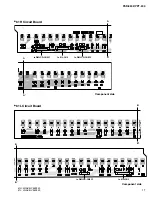
4-3-2 Remove the twelve (12) screws marked [150B]. The
PNAM circuit board 1/3 can then be removed. (Fig. 2)
4-4
PNAM circuit board (2/3)
(Time required: About 3 minutes)
4-4-1 Remove the nine (9) screws marked [150C]. The
PNAM circuit board 2/3 can then be removed. (Fig. 2)
5.
Speaker
(Time required: About 3 minutes)
5-1
Remove the lower case assembly. (See procedure 1)
5-2
Remove the four (4) screws marked [30]. The
speaker can then be removed. (Fig. 2)
∗
The right and left speakers can be removed in the
same way.
6.
SP Grille
(Time required: About 3 minutes)
6-1
Remove the lower case assembly. (See procedure 1)
6-2
Set the four (4) [A]s parallel to the groove in the upper
case assembly and remove the SP grille. (Fig. 2)
∗
The right and left SP grilles can be removed in the
same way.
Knob
(Master Volume)
(Fig.3)
Conductor side
Rubber Connector
Rubber Connector
DMLCD
LCD
Rubber Connector
Back Light Assembly
LCD Holder


