Metering
19
ProMix 01 User’s Guide
1. Press [METER].
The METER LCD function
appears.
2. To turn the Peak Hold func-
tion ON and OFF, press
[ENTER] or use the PARAM-
ETER wheel.
3. Use the [
√
] [
®
] cursor but-
tons or press [ENTER] to
switch between the two
METER displays.
Metering
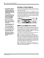
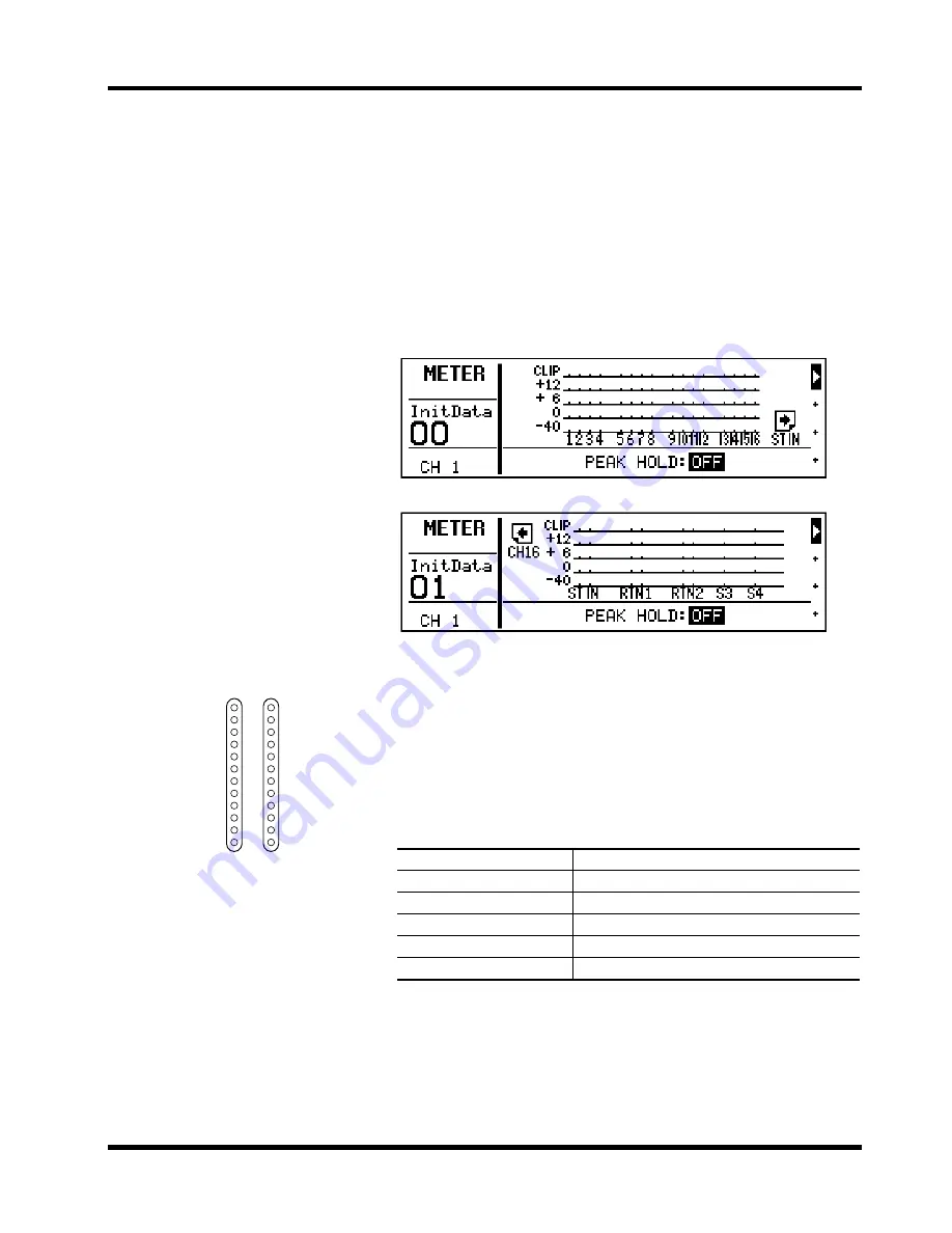
ProMix 01 features comprehensive signal level metering. Input chan-
nels, the stereo input channel, RTN1, RTN2, SEND3, and SEND4 are
all metered using the METER LCD function. The stereo output is
metered using the dedicated 12-segment LED meters. Peak hold is
available for all meters.
The METER LCD function consists of two displays. One shows the
16 input channels. The other, the stereo input (ST IN), RTN1, RTN2,
SEND3, and SEND4. Both displays are shown below.
The Peak Hold function can be turned ON and OFF on either display.
Peak hold levels are cancelled when Peak Hold is turned OFF or
another LCD function is selected. The stereo output meter peak hold
is not affected when other LCD functions are selected.
The following table lists the meter signal source points.
When the stereo output meter’s 0dB LED lights up, the DIGITAL REC
OUT still has 20dB of headroom.
Note:
It’s OK for signal levels to reach CLIP occasionally. If CLIP is
reached often, however, back off the GAIN control a little, otherwise sig-
nal distortion may occur.
Signal
Source Point
Input channel
Post GAIN and A/D converter—pre phase and EQ
Stereo input channel (ST IN)
Post GAIN and A/D converter—pre phase and EQ
Stereo output
Post fader and balance—pre D/A converter
RTN1, RTN2
Post internal effect—pre EQ and fader
SEND3, SEND4
Post fader—pre D/A converter
Note:
When the STEREO OUT XLRs are used with unbalanced con-
nectors, their maximum output level is reduced by 6dB. This means that
the STEREO OUT signal actually clips when the 15dB LED lights up,
which is 5dB before the CLIP LED.
CLIP
15
12
9
6
3
0
–6
–12
–18
–24
–40
L
R
Stereo output meters
Summary of Contents for Programmable Mixer 01
Page 4: ...ii ProMix 01 User s Guide...
Page 18: ...10 Chapter 1 Touring ProMix 01 ProMix 01 User s Guide...
Page 24: ...16 Chapter 2 User Interface ProMix 01 User s Guide...
Page 36: ...28 Chapter 3 Mixer Functions ProMix 01 User s Guide...
Page 68: ...60 Chapter 6 Groups and Pairs ProMix 01 User s Guide...
Page 74: ...66 Chapter 7 Scene Memories ProMix 01 User s Guide...
Page 96: ...88 Chapter 9 MIDI ProMix 01 User s Guide...
Page 102: ...94 Troubleshooting ProMix 01 User s Guide...
Page 116: ...108 Appendix ProMix 01 User s Guide...
Page 154: ...YAMAHA CORPORATION VS17170 IP 95 01 5000 AP Printed in Japan P O Box 1 Hamamatsu Japan...


