PSR-E413
32
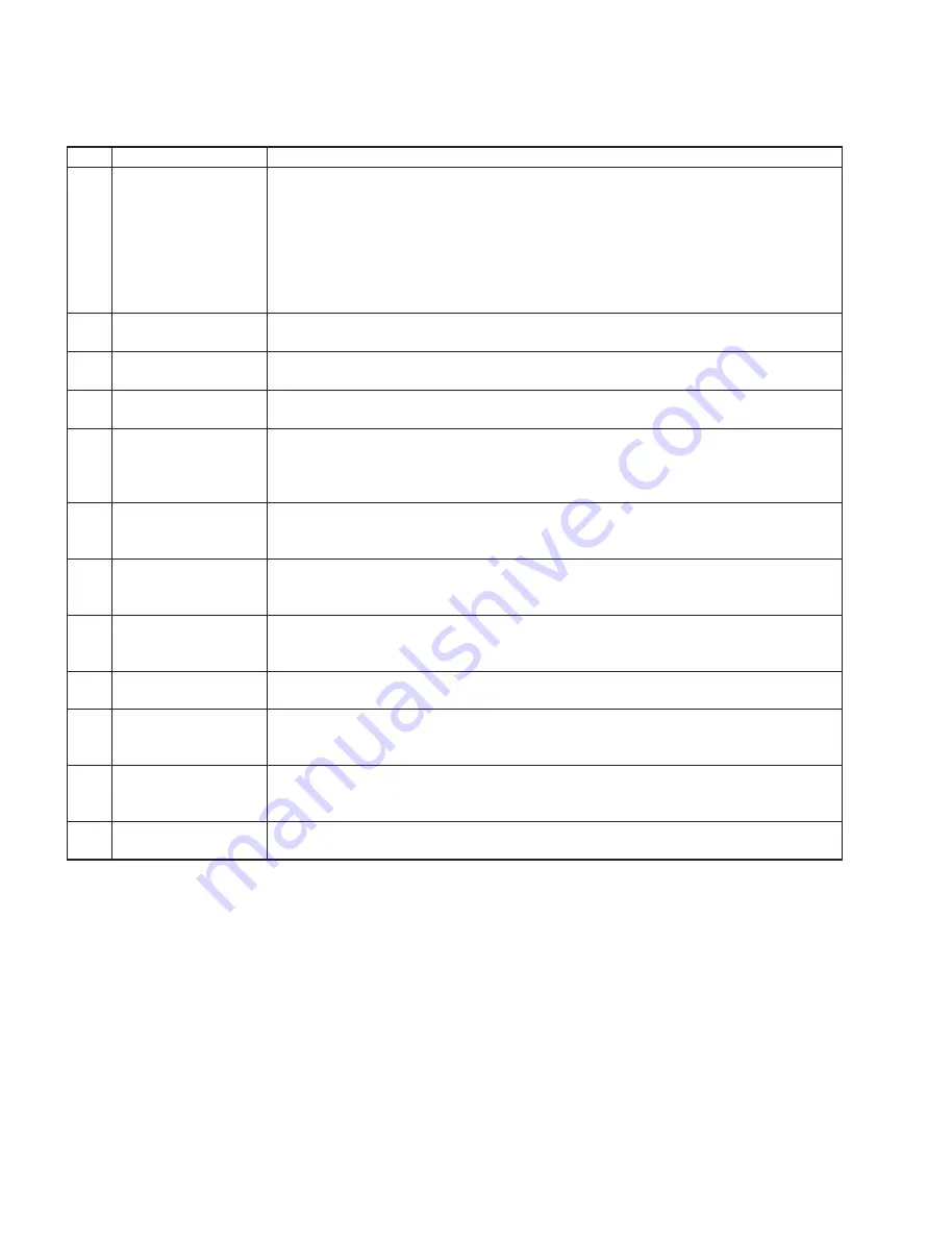
TEST No
LCD display
Test descriptions, judging conditions, etc.
20
SW Chk
020
Checks the switches and LEDs on the panel. Press the switches as shown in the LCD. When a switch
is pressed, a sound is played at the prescribed pitch. (Refer to the Switch Test Item List on the next
page.) When a switch with LED is turned on, the LED will light up.
Make sure that “
SW OK
” is displayed on the LCD when all the switches are pressed as indicated. For
the Dial item, make sure that “
Up
” is indicated when the encoder knob is turned clockwise, and “
Dwn
”
when turned counterclockwise. For the Knob item, make sure that “
Lo
” is indicated when the rotary knob
is turned fully counterclockwise, “
Hi
” when turned fully clockwise, and “
C
” when set to the center. To
cancel the operation halfway, press the lowest key (white key C1) to return to the item selection display.
21
A. LedChk
021
Make sure that all the LEDs on the panel are turned on.
28
LCD On
028
Make sure that all the dots on the LCD are turned on.
29
LCD Off
029
Make sure that all the dots on the LCD are turned off.
31
PD1 Chk
031
Connect a footswitch (FC-4 or FC-5) to the [SUSTAIN] jack.
Press the [START/STOP] button to start the test and check that C3 is played when the pedal is de-
pressed (ON), and C4 is played when the pedal is released (OFF).
Make sure that “
PD1 OK
” is displayed on the LCD.
33
PB Chk
033
C3 is played when the [PITCH BEND] wheel is turned toward you to the minimum position (DW),
and C4 is played when the wheel is turned away from you to the maximum position (UP).
Make sure that “
PB OK
” is displayed on the LCD.
37
MIDI Chk
037
Connect a PC which has installed the driver and main unit [USB] terminal with a USB cable. Set the
through mode on PC and execute the test.
Confi rm that the C4 note is output and “
MIDI OK
” is displayed on the LCD.
41
Rom Chk2
041
Checks the ROM connected to the CPU bus.
Make sure that “
Rom OK
” is displayed on the LCD.
It will take about 15 seconds for the check.
42
Ram Chk2
042
Checks the RAM connected to the CPU bus.
Make sure that “
Ram OK
” is displayed on the LCD.
45
FRomChk2
045
Checks the FROM connected to the CPU bus.
Make sure that “
FRom OK
” is displayed on the LCD.
It will take about 30 seconds for the check.
47
Factory
047
Initializes the entire backup area to reset to the factory default.
“
Fact
” is displayed on the LCD during the test.
“
Fact End
” is displayed on the LCD when the test is fi nished.
48
TestExit
048
This will leave the test program and change to the play mode.
•
Other Tests
Popping Noise Check
Connect the oscilloscope to the L/R of the [PHONES/OUTPUT] jack and turn on and then off the [STANDBY/ON] switch. Make
sure that popping noise level is 1.0 Vp-p or less, and that no abnormal sound or popping noise is output from the speakers.
Noise Level Check
Connect the level meter (with JIS-C fi lter) to the L/R of the [PHONES/OUTPUT] jack. (33
Ω
load)
Set the [MASTER VOLUME] to the maximum level and check the noise level.
· PHONES L, R: –78 dBu or less