6
5
4
3
H
A
B
C
D
E
F
G
1
2
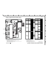
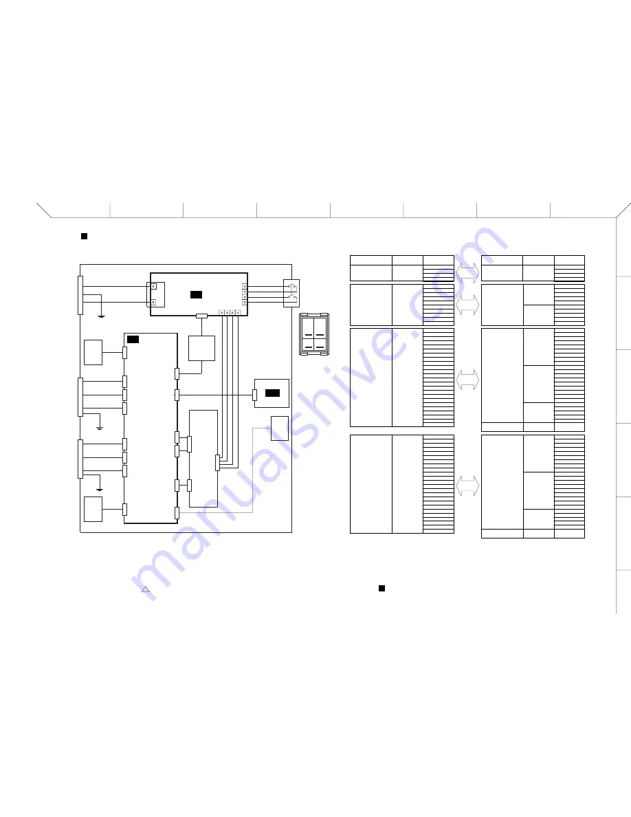
OVERALL CONNECTOR CIRCUIT DIAGRAM (PW800W)
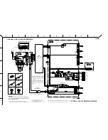
OVERALL CONNECTOR CIRCUIT DIAGRAM (PW800W)
PW800W
28CA2-8831513-01
2
28CA2-8831513-02
A1
B2
A3
B4
CN1
AC/AD
CONVERTOR
Circuit Board name
(シート名)
CN number
(CN番号)
PIN number
(ピン番号)
1
2
3
4
5
6
7
8
9
1
2
3
4
5
6
7
8
9
1
2
3
4
5
CN11
CN17
CN15
Earth lag
(アースラグ)
DC Circuit Board
1
2
3
4
5
6
7
8
9
1
2
3
4
5
6
7
8
9
1
2
3
4
5
CN16
CN12
CN19
Earth lag
(アースラグ)
DC Circuit Board
DC Circuit Board
DC Circuit Board
1
2
3
4
5
1
2
3
4
5
CN7
CN8
K10
K11
K12
K13
AC Circuit Board
Circuit Board name
(シート名)
CN number
(CN番号)
PIN number
(ピン番号)
1
2
3
4
5
6
7
8
9
10
11
12
13
14
15
16
17
18
19
20
21
22
23
24
ROUND
CONNECTOR
[DC OUTPUT]
1
2
3
4
5
6
7
8
9
10
11
12
13
14
15
16
17
18
19
20
21
22
23
24
B1
B2
B3
A1
A2
A3
A4
A5
B4
B5
CN2
AC/DC
CONVERTOR
(丸型コネクタ)
ROUND
CONNECTOR
[DC PARALLEL
INPUT]
(丸型コネクタ)
NOTE: Pin on the same line are connected to each other.
(同一のピン同士が接続されます。)
(接続がないピンについては、上記に表していません。)
Pins which are not to be connected are not shown above.
( [ ] 内はパネル上の印字を示します。)
Characters in the brackets "[ ]" indicate the printing on the panel.
NOTE: Characters in the brackets "[ ]" indicate the printing on the panel.
( [ ] 内はパネル上の印字を示します。)
(※※印部分の接続は右側に詳細を示します。その他の接続はコネクタの両端で全ピン1対1の対応です。)
Double reference marks "
※※
" indicate that the connections are show on the right in detail.
(K**はファストンタブを示します。)
The letter "K" with a number at the right indicates a faston tab.
(POWER SUPPLY)
(POWER SUPPLY)
※※
※※
※※
[POWER
ON/OFF]
POWER
SWITCH
1a
1
2a
2
K6
K7
K8
K9
K10
K5
K4
K11K12 K13
CN6
(3P)
FG
FG
L
N
FG
[DC PARALLEL
INPUT]
[DC OUTPUT]
ROUND CONNECTOR
ROUND CONNECTOR
(丸型コネクタ)
(丸型コネクタ)
[AC IN]
AC INLET
CN10
(3P)
CN14
(2P)
CN7
(6P)
CN8
(7P)
CN9
(5P)
CN6
(3P)
CN18
(3P)
CN19
(5P)
CN12
(10P)
CN16
(9P)
※※
CN15
(5P)
CN17
(10P)
(24P)
(3P)
(24P)
CN11
(9P)
CN13
(3P)
CN2
(2P)
CN2
(10P)
CN1
(6P)
CN21
(3P)
AC
DC
LED
TRANS-
FORMER
(AC/DC
CONVERTOR)
POWER SUPPLY
UNIT
FAN
FAN
FAN
(SW端子配置図)
1
Switch connector
arrangement diagram
2
1a
2a


