background image

Contents

V-belt ............................................  57
Drive chain housing ......................  59
Brake and parking brake  ..............  60
Skis and ski runners  .....................  62
Steering system  ...........................  63
Drive track and slide runners  .......  64
High-profile pattern drive track  .....  67
Lubrication ....................................  67
Replacing a headlight bulb  ...........  67
Adjusting the headlight beams  .....  69
Fittings and fasteners  ...................  69
Battery ..........................................  69
Replacing a fuse  ..........................  69

Troubleshooting ............................. 71

Storage ............................................ 74

Specifications ................................. 76

Consumer information.................... 78

Identification number records  .......  78
YAMAHA MOTOR 

CORPORATION, 
U.S.A. SNOWMOBILE 
LIMITED WARRANTY ...............  79

YAMAHA EXTENDED SERVICE 

(Y.E.S.).......................................  82

U8GK11E0.book  Page 2  Wednesday, April 11, 2007  9:51 AM

Summary of Contents for PZ50RTX

Page 1: ...OWNER S MANUAL PZ50RTX PZ50GTX PZ50MTX PZ50VTX 8GK 28199 11 LIT 12628 02 68 ...

Page 2: ...ESU10040 ...

Page 3: ...ve any questions concerning the operation or main tenance of your snowmobile please consult a Yamaha dealer To maintain the high quality and performance of this snowmobile it is important that you and your Yamaha dealer pay close attention to the recommended maintenance schedules and operating instructions contained within this manual PZ50RTX PZ50GTX PZ50MTX PZ50VTX OWNER S MANUAL 2007 by Yamaha M...

Page 4: ...aler This manual should be considered a per manent part of this snowmobile and should remain with the snowmobile when resold Particularly important information is distin guished in this manual by the following nota tions The Safety Alert Symbol means ATTEN TION BECOME ALERT YOUR SAFETY IS INVOLVED WARNING EWS00020 Failure to follow WARNING instructions could result in severe injury or death to the...

Page 5: ...s PZ50VT 18 Shroud and covers 19 Drive guard 20 V belt holder PZ50VT 20 Passenger grip warmer switch PZ50VT 21 Backrest PZ50VT 21 Storage pouch 21 Rear carrier PZ50VT 22 Fuel 22 Suspension 24 Pre operation checks 31 Pre operation check list 31 Operation 33 Starting the engine 33 Break in 33 Riding your snowmobile 34 Maximizing drive track life 37 Strap PZ50MT 38 Driving 38 Stopping the engine 39 T...

Page 6: ... pattern drive track 67 Lubrication 67 Replacing a headlight bulb 67 Adjusting the headlight beams 69 Fittings and fasteners 69 Battery 69 Replacing a fuse 69 Troubleshooting 71 Storage 74 Specifications 76 Consumer information 78 Identification number records 78 YAMAHA MOTOR CORPORATION U S A SNOWMOBILE LIMITED WARRANTY 79 YAMAHA EXTENDED SERVICE Y E S 82 ...

Page 7: ...Your ability to operate the snowmobile is re duced by the influence of alcohol or drugs 5 For safety and proper care of the snow mobile always perform the pre operation checks on page 31 before starting the en gine Check the throttle brake and steer ing for proper operation every time before starting the engine Make sure that the throttle lever moves freely and it returns to the home position when...

Page 8: ... the engine to transport the snowmobile in or out of the building Open the outside doors exhaust fumes are dangerous 2 Be careful where you ride There may be obstacles hidden beneath the snow Stay on established trails to minimize your ex posure to hazards Ride slowly and cau tiously when you ride off of established trails Hitting a rock or stump or running into wires could cause an accident and i...

Page 9: ...approved by Yamaha or the removal of original equipment may render your snowmobile unsafe for use that may cause severe personal injury Modifica tions may also make the snowmobile ille gal to use 4 Never store the snowmobile with fuel in the fuel tank inside a building where igni tion sources are present such as hot wa ter and space heaters an open flame sparks clothes dryers and the like Allow th...

Page 10: ...fety information 4 ESU10211 Location of the important labels Please read the following labels carefully before operating this snowmobile NOTE Maintain or replace safety and instruction labels as necessary ...

Page 11: ...Safety information 5 ...

Page 12: ...Safety information 6 ...

Page 13: ...l filler cap 5 Battery 6 Main fuse 7 Fuse box 8 Coolant reservoir 9 V belt holder PZ50VT 10 Strap PZ50MT 11 Passenger grip warmer switch PZ50VT 12 Backrest PZ50VT 13 Tail brake light 14 Rear carrier PZ50VT 15 Slide rail suspension 16 Drive track 17 Idle adjusting screw ...

Page 14: ...ary DC jack PZ50VT 11 RESET button 12 SELECT button 13 Fuel level warning indicator 14 Oil level warning indicator 15 Coolant temperature warning indicator 16 Self diagnosis warning indicator 17 Speedometer 18 Odometer tripmeter engine speed meter 19 Fuel meter and grip thumb warmer level in dicator 20 Fuel meter indicator 21 Drive D indicator light 22 Reverse R indicator light 23 Drive select swi...

Page 15: ...y varying the throttle position Because the throttle is spring loaded the snowmobile will decelerate and the engine will return to idle when it is released WARNING EWS00030 Check the throttle brake and steering for proper operation before starting the en gine See page 31 ESU10321 Engine overheating prevention system This model is equipped with a system which prevents overheating when the engine is...

Page 16: ...rouble NOTE When the T O R S is activated the warn ing light and self diagnosis warning indica tor will flash and the two digit code 84 will flash in the meter display The T O R S monitors the condition of the throttle position sensor speedometer as sembly and speed sensor and will operate if any of the monitored items is disconnect ed or is malfunctioning Idling starting Running Trouble Throttle ...

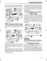
Page 17: ...ator which shows the grip warmer or the thumb warm er level After the main switch is turned on the warning light the low coolant temperature indicator light the knock control system KCS indica tor light the drive D indicator light the re verse R indicator light and all segments of the meter display turn on and off once The grip warmer level is initially displayed for 5 seconds then the display swi...

Page 18: ...ight The low coolant temperature indicator light comes on when the coolant temperature is low and informs the rider that the snowmobile should be warmed up After the engine is started warm it up until the indicator light goes off The snowmobile can be operated normally af ter the indicator light goes off NOTE Operate the snowmobile at low speeds when the low coolant temperature indicator light is ...

Page 19: ...he snowmobile is shifted into drive or reverse The drive D indicator light comes on when the transmission is in drive forward The reverse R indicator light comes on when the transmission is in reverse The snowmobile can be shifted into drive or reverse by pushing the drive select switch See page 16 for drive select switch opera tion ESU10431 Fuel meter and grip thumb warmer level indicator The fue...

Page 20: ...nd the display switches to the thumb warmer level NOTE The grip thumb warmer level is displayed for 5 seconds after releasing the grip thumb warmer adjustment switch then the display switches to the fuel meter When the engine is started the grip thumb warmer levels are set to the levels selected when the engine is stopped ESU10450 Fuel level warning indicator The fuel level warning indicator indic...

Page 21: ...ecking procedures and add engine oil if necessary ESU10511 Coolant temperature warning indicator If the engine overheats the coolant tempera ture warning indicator and the warning light come on When this occurs stop the engine immediately and allow the engine to cool down and then check the coolant level in the coolant reservoir See page 56 for checking procedures CAUTION ECS00040 Do not operate t...

Page 22: ...is in drive forward The reverse R indicator light comes on when the transmission is in reverse CAUTION ECS00050 Do not shift from drive to reverse or from reverse to drive while the snowmobile is moving Otherwise the drive system could be damaged ESU10530 Engine stop switch The engine stop switch is used to stop the en gine in an emergency Simply push the stop switch to stop the engine To start th...

Page 23: ...d lev el ESU10690 Auxiliary DC jack PZ50VT The auxiliary DC jack is located in the front panel and can be used for accessories NOTE The auxiliary DC jack cannot be used if the engine is not running To use the auxiliary DC jack 1 Start the engine 2 Open the auxiliary DC jack cap and then insert the accessory power plug into the jack NOTE After using the auxiliary DC jack be sure to remove the acces...

Page 24: ... side for service ESU10580 Parking brake lever When parking the snowmobile or starting the engine apply the parking brake by moving the parking brake lever to the left To release the parking brake move the park ing brake lever to the right WARNING EWS00060 Always set the parking brake before at tempting to start the engine Never run the snowmobile with the park ing brake applied This may overheat ...

Page 25: ...cing with the shroud open Do not touch the hot muffler and engine during or immediately after operation ESU10730 Shroud and covers Securely fasten the shroud and covers before operating the snowmobile See page 45 for removal and installation procedures PZ50RT PZ50GT PZ50MT PZ50VT 1 Shroud 1 Air filter case cover 2 Front cover 1 Top cover 2 Right upper cover 3 Right side cover 4 Right lower cover 1...

Page 26: ... and installing the covers ESU10750 Drive guard The drive guard is designed to cover the V belt clutch and V belt in case parts break or come loose WARNING EWS00400 Make sure that the drive guard is tight ened securely before operating the snowmobile Never run the engine with the V belt or drive guard removed ESU10770 V belt holder PZ50VT Keep a spare V belt for emergency use by placing it into th...

Page 27: ...ighten the bolts and close the zipper WARNING EWS00130 Do not sit on the backrest ESU12991 Storage pouch The storage pouch is located behind the front bumper Use the storage pouch to store the tool kit spare parts such as the V belt PZ50RT PZ50GT PZ50MT or other small items To remove the storage pouch Unfasten the storage pouch upper and lower buckles and then pull the storage pouch off as shown 1...

Page 28: ...e spare V belt PZ50RT PZ50GT PZ50MT Keep a spare V belt for emergency use by storing it in the storage pouch NOTE When storing a spare V belt in the storage pouch be sure to secure it with the hook and loop fastener ESU10840 Rear carrier PZ50VT The rear carrier is located at the rear of the snowmobile WARNING EWS00140 Do not use the rear carrier to lift the snow mobile The snowmobile could fall wh...

Page 29: ...higher or a research octane number of 95 or higher If the recommended fuel is not used the en gine may not perform as it should CAUTION ECS00080 Oxygenated fuels gasohol containing a maximum 5 of ethanol can be used although richer jetting may be required to prevent engine damage Consult a Yamaha dealer Gasohol containing methanol is not recommended Make sure that snow or ice does not en ter the f...

Page 30: ...orm or damage the shock ab sorber in any way Do not dispose of a worn or damaged shock absorber by yourself Take the unit to a Yamaha dealer ESU10900 Adjusting the ski spring preload CAUTION ECS00250 The left and right ski spring preload must be set to the same setting Uneven set tings can cause poor handling and loss of stability The spring preload can be adjusted by turning the spring preload ad...

Page 31: ...ECS00710 Make sure that there is no load on the shock absorbers and that they are fully ex tended before making any air pressure ad justments 1 Place the snowmobile on a level surface and apply the parking brake 2 Lift the front of the snowmobile onto a suitable stand to raise the skis off the ground 3 Remove the air valve cap from the shock absorber 4 Install the hose connector of the shock absor...

Page 32: ... the air valve cap NOTE If the front suspension bottoms too easily or rolls too much during cornering increase the air pressure by 34 kPa 0 3 kgf cm 5 psi If the suspension is too firm and you want a more compliant ride decrease the air pres sure by 34 kPa 0 3 kgf cm 5 psi ESU10921 Adjusting the ski damping force PZ50GT CAUTION ECS00260 The damping forces for the left and right ski shock absorbers...

Page 33: ...nsion spring preload The spring preload can be adjusted by turning the spring preload adjusting ring on the center shock absorber and the spring preload adjust er on the rear shock absorber PZ50GT PZ50MT 1 Compression damping force adjusting knob Compression damping setting Minimum soft 12 click s in direction b Standard 7 click s in direction b Maximum hard 2 click s in direction b With the adjus...

Page 34: ... the center shock absorber spring seat length or spring preload adjusting ring position Minimum soft PZ50GT PZ50MT PZ50VT 1 PZ50RT 112 5 mm 4 43 in Standard PZ50GT PZ50MT 1 PZ50VT 3 PZ50RT 113 5mm 4 47 in Maximum hard PZ50GT PZ50MT PZ50VT 5 PZ50RT 123 5 mm 4 86 in The spring seat length changes ap proximately 1 5 mm 0 06 in with each full turn of the adjusting ring Spring preload setting at the re...

Page 35: ...AUTION ECS00300 Do not continue to turn the adjusting screw in direction a after it stops The shock absorber can be damaged and damping force adjustments cannot be made Do not turn the adjusting screw in direc tion b more than 20 click s Even if the adjusting screw is continually turned af ter 20 click s there will be no change in the damping force Be sure to stop the adjusting screw at a position...

Page 36: ... in place CAUTION ECS00310 When using the two wrenches included in the owner s tool kit make sure that they are situated at a right angle to the control rod as shown and that they are tightly fitted to the locknut and the con trol rod adjusting nut The left and right adjusting nuts must be set to the same position Uneven set tings can cause poor handling and loss of stability 1 Locknut 2 Control r...

Page 37: ...t inspected and repaired before operating the snowmobile ESU11080 Pre operation check list ITEM CHECKS PAGE Fuel Check fuel level Refuel if necessary Check fuel line for leakage 23 Engine oil Check oil level in engine If necessary add recommended oil to specified level Check vehicle for oil leakage 52 Coolant Check coolant level Add if necessary 56 V belt Check for wear and damage Replace if neces...

Page 38: ...ear and damage If necessary have Yamaha dealer replace track 64 Slide runners Check for wear and damage If necessary have Yamaha dealer replace slide runners 64 Steering Check for excessive free play 63 Strap PZ50MT Check for damage Replace if necessary 38 Lights signals and switch es Check operation Correct if necessary 17 16 67 69 Throttle lever Make sure that operation is smooth and spring back...

Page 39: ...ssible to preserve the battery Do not crank the engine more than 10 sec onds on any one attempt ESU11320 Break in There is never a more important period in the life of your engine than the period between 0 and 500 km 300 mi For this reason you should read the following material carefully Since the engine is brand new do not put an excessive load on it for the first 500 km 300 mi The various parts ...

Page 40: ...ou ride always perform the pre oper ation checks listed on page 31 The short time spent checking the condition of the snowmo bile will be rewarded with added safety and a more reliable snowmobile Always wear the proper clothing for both warmth and to help protect you from injury if an accident occurs Become familiar with operating your snowmo bile at low speeds even if you are an experi enced ride...

Page 41: ...he snow mobile to tip If your snowmobile begins to tip while turning lean more into the turn to regain balance If necessary gradually let off on the throttle or steer to the outside of the turn Remember Avoid higher speeds until you are thoroughly familiar with the operation of your snowmo bile Riding uphill You should practice first on gentle slopes Try more difficult climbs only after you have d...

Page 42: ...on your weight towards the uphill side A recommended riding position is to kneel with the knee of your downhill leg on the seat and the foot of your uphill leg on the running board This position will make it easi er for you to shift your body weight as needed Snow and ice are slippery so be prepared for the possibility that your snowmobile could be gin to slip sideways on the slope If this hap pen...

Page 43: ...result in loss of braking ability and snowmobile control which could cause an accident Always check the drive track for damage or maladjustment before operating the snowmobile Do not operate the snowmobile if you find damage to the drive track CAUTION ECS00350 Ride on fresh snow frequently Operating on ice or hard packed snow will rapidly wear the slide runners ESU11350 Maximizing drive track life...

Page 44: ...ill to maintain balance during traverse side hill riding Only experienced oper ators should traverse slopes steep enough to require strap use Keep the right hand on the right handle bar grip for steering and grip the strap with the left hand to shift weight uphill for balance during traverse riding Ride cautiously while using the strap Do not accelerate or decelerate abruptly while holding onto th...

Page 45: ...operating the snowmobile in re verse CAUTION ECS00050 Do not shift from drive to reverse or from reverse to drive while the snowmobile is moving Otherwise the drive system could be damaged NOTE The reverse buzzer beeps while the transmis sion is in reverse 2 Release the parking brake by moving the parking brake lever to the right 3 Press the throttle lever slowly to move the snowmobile 4 Turn the ...

Page 46: ... or truck put a tight fitting cover on the snowmobile A cover specifically designed for your snowmobile is best This will help keep foreign objects out of the cooling vents and also help protect the snowmo bile against damage from debris on the road If transporting the snowmobile in an open trailer or truck in areas where road salt is used coat metal suspension surfaces light ly with oil or anothe...

Page 47: ...NLY FUNCTION TO ENSURE CLEANER AIR BUT ARE ALSO VITAL TO PROPER EN GINE OPERATION AND MAXIMUM PERFORMANCE IN THE FOLLOWING PERIODIC MAINTENANCE CHARTS THE SERVICES RELATED TO EMISSION CONTROL ARE GROUPED SEPARATELY THESE SERVICES REQUIRE SPECIALIZED DATA KNOWL EDGE AND EQUIPMENT YAMAHA DEALERS ARE TRAINED AND EQUIPPED TO PER FORM THESE PARTICULAR SERVICES ESU11460 Periodic maintenance chart for th...

Page 48: ...recommended that these items be serviced by a Yamaha dealer Exhaust system Check for leakage Tighten or replace gasket if necessary ITEM REMARKS INITIAL EVERY PAGE 1 month or 800 km 500 mi 40 hr Seasonally or 4000 km 2500 mi 200 hr ...

Page 49: ...d bushings for wear for primary Inspect ramp shoes bushings for wear for secondary Replace if necessary Lubricate with specified grease Drive chain Check chain slack Adjust if necessary Initial at 500 km 300 mi and every 800 km 500 mi thereafter 59 Drive chain oil Check oil level 59 Change 59 Brake and parking brake Adjust free play and or replace pads if necessary 60 Change brake fluid See NOTE f...

Page 50: ...ose every four years or if cracked or damaged Steering system Check toe out Adjust if necessary 63 Steering bearings Check bearing assemblies for looseness Lubricate with specified grease Ski and front sus pension Lubricate with specified grease 67 Suspension compo nent Lubricate with specified grease 67 Fittings and fasten ers Make sure that all nuts bolts and screws are properly tight ened Tight...

Page 51: ...your snowmobile to a Yamaha dealer to check the torque settings and adjust them if necessary ESU11761 Removing and installing the shroud and covers Shroud front cover and air filter case cover To open the shroud and remove the front cov er and air filter case cover 1 Unhook the latch and then slide the front cover upward PZ50RT PZ50GT PZ50MT Unhook the shroud latches and then slowly raise the shro...

Page 52: ... PZ50MT PZ50RT PZ50GT PZ50MT Slowly lower the shroud to the original position and then hook the shroud latch es PZ50VT Left side cover To remove the left side cover Loosen the fasteners and then remove the left side cover To install the left side cover Place the left side cover in the original posi tion and then tighten the fasteners Right side cover To remove the right side cover Loosen the quick...

Page 53: ...0MT To remove the right upper cover 1 Remove the top cover See the above procedure 2 Remove the right upper cover by remov ing the bolts To install the right upper cover 1 Place the right upper cover in the original position and then install and tighten the bolts to the specified torque 2 Install the top cover Left and right upper covers PZ50VT To remove an upper cover 1 Open the shroud See the ab...

Page 54: ...covers be sure to tighten all fasteners securely ESU11780 Checking the spark plugs The spark plug is an important engine compo nent and is easy to inspect The condition of the spark plug can indicate the condition of the engine Check the coloration on the white porcelain insulator around the center electrode The ideal coloration at this point is a medium to a light tan color for a snowmobile that ...

Page 55: ...reach Before installing any spark plug measure the electrode gap with a wire thickness gauge and adjust to specification When installing the spark plug always clean the gasket surface Wipe off any grime from the threads and tighten the spark plug to the specified torque CAUTION ECS00380 Make sure that the spark plug caps are se curely installed Otherwise the spark plug caps could be damaged due to...

Page 56: ...e play if necessary ESU11861 Checking the throttle override system T O R S Check the T O R S for proper operation WARNING EWS00351 When checking the T O R S Make sure that the parking brake is ap plied Make sure that the throttle lever moves smoothly Do not rev the engine to the point that the clutch engages otherwise the snow mobile could start moving which could cause an accident 1 Start the eng...

Page 57: ...nd consult a Yamaha dealer ESU11891 Checking the air filter Always check that there is no snow under the air filter element 1 Remove the front cover PZ50RT PZ50GT PZ50MT or open the shroud PZ50VT and then remove the air filter case cover See page 45 for removal procedures 2 Unhook the air filter element frame fas teners 3 Lift up the air filter element frame and check the air filter element If the...

Page 58: ...de CAUTION ECS00430 The drive chain gears and V belt clutch should be adjusted when operating above a high altitude of 900 m 3000 ft Consult a Yamaha dealer ESU11950 Valve clearance The valve clearance changes with use result ing in improper air fuel mixture and or engine noise To prevent this from occurring the valve clearance must be adjusted by a Yamaha dealer at the intervals specified in the ...

Page 59: ...ect the oil level gauge coupler be fore removing the oil filler cap otherwise the cable could twist and break 5 Remove the oil filler cap wipe the dipstick clean insert it back into the oil filler hole without screwing it in and then remove it again to check the oil level NOTE The engine oil should be between the H and L level marks on the dipstick 6 If the engine oil is below the L level mark add...

Page 60: ... surface and apply the parking brake 2 Start the engine warm it up for several minutes and then turn it off 3 Remove the right side cover PZ50RT PZ50GT PZ50MT or open the shroud and remove the right upper cover and the right side cover PZ50VT See page 45 for removal procedure 4 Remove the bottom panel and the right lower cover 5 Place an oil pan under the oil tank to col lect the used oil 6 Discon...

Page 61: ...checking it for oil leakage If oil is leaking immediately turn the engine off and make sure that the en gine oil drain bolt oil tank drain bolt and the oil filler cap are installed correctly 15 Turn the engine off and then connect the oil level gauge coupler 16 Install the bottom panel and the right low er cover 17 Install the right side cover PZ50RT PZ50GT PZ50MT or install the right side cover a...

Page 62: ...t up per cover See page 45 for removal pro cedures 2 Check the coolant level in the coolant reservoir when the engine is cold If the coolant level is below the COLD LEVEL mark add soft water until it reaches the COLD LEVEL mark See the following section Replenishing the coolant for more details CAUTION ECS00490 Hard water or salt water is harmful to the engine parts You may use boiled or dis tille...

Page 63: ... belt or drive guard removed The V belt should be checked before each ride To check the V belt 1 Remove the left side cover PZ50RT PZ50GT PZ50MT or open the shroud and remove the left upper cover and the left side cover PZ50VT See page 45 for removal procedure 2 Remove the drive guard 3 Check the V belt for wear and damage Replace if necessary 1 COLD LEVEL mark 2 Coolant reservoir cap Recommended ...

Page 64: ...t ment CAUTION ECS00520 To ensure proper clutch performance as the V belt wears it is necessary to adjust the gap between the secondary fixed sheave and the secondary sliding sheave by changing the positions of the spacers Have a Yamaha dealer make this adjust ment NOTE Apply the parking brake before replacing the V belt 1 Remove the left side cover PZ50RT PZ50GT PZ50MT or open the shroud and remo...

Page 65: ...e still hot with any part of your body or cloth ing during inspection or repair To check the drive chain housing oil level 1 Place the snowmobile on a level surface 2 Remove the right side cover See page 45 for removal procedures 3 Remove the dipstick wipe it off with a clean rag and then insert it back into the filler hole 4 Remove the dipstick and check that the oil level is within the range sho...

Page 66: ...lt in place while tightening the locknut 5 Install the right side cover ESU12130 Brake and parking brake WARNING EWS00440 A soft spongy feeling in the brake lever indicates a failure in the brake system Do not operate the snowmobile if you find any problems in the brake system You could lose braking ability which could lead to an accident Ask a Yamaha dealer to inspect and repair the brake system ...

Page 67: ...e to have a Yamaha dealer make this adjustment 1 Loosen the parking brake pad locknut and the parking brake pad adjusting bolt 2 Loosen the parking brake cable locknut 3 Turn the parking brake cable adjusting bolt in or out to adjust the cable length 4 Tighten the parking brake cable locknut 5 Turn the parking brake pad adjusting bolt in or out to adjust the clearance between the parking brake pad...

Page 68: ...l surface Check that the brake fluid is above the lower level and replenish when necessary Changing the brake fluid WARNING EWS00470 Make sure that the brake fluid and the above parts are replaced by a Yamaha dealer Brake fluid replacement is necessary when the following components are replaced during the periodic maintenance or if they are dam aged or leaking All oil seals of the master cylinder ...

Page 69: ...toe out distance A distance B is within specification 3 If the alignment is not correct consult a Yamaha dealer ESU12151 Steering system Check the handlebar for excessive free play To check the handlebar 1 Push the handlebar up and down and back and forth 2 Turn the handlebar slightly to the right and left If excessive free play is felt consult a Yamaha dealer 1 Ski wear limit Ski runner wear limi...

Page 70: ...depth where fabric reinforcement material is visible or support rods are broken Otherwise track damage or fail ure could result in loss of braking ability and snowmobile control which could cause an accident Checking the drive track WARNING EWS00490 Do not operate the snowmobile if you find damage to the drive track or if it has been maladjusted Drive track damage or failure could result in loss o...

Page 71: ... stand to raise the drive track off the ground 2 Loosen the rear axle nut 3 Start the engine and rotate the drive track one or two turns Stop the engine 4 Check the drive track alignment with the slide runners If the alignment is incorrect align the drive track by turning the left and right adjusting nuts Standard drive track deflection 30 0 35 0 mm 1 18 1 38 in 1 Rear axle nut 1 Slide runner Driv...

Page 72: ...am age If the slide runners reach the wear limit they should be replaced CAUTION ECS00350 Ride on fresh snow frequently Operating on ice or hard packed snow will rapidly wear the slide runners 1 Forward 2 Gap 3 Slide runner 4 Drive track 5 Slide metal 1 Forward 2 Gap 3 Slide runner 4 Drive track 5 Slide metal Drive track deflection More than specified Less than specified Left adjusting nut Turn in...

Page 73: ...d snow dirt or grass will result in rapid wear or damage to the track and slide runners from lack of snow which serves as a lubricant ESU12200 Lubrication Lubricate the following points with the speci fied grease WARNING EWS00520 Apply a dab of grease onto the cable end only Do not grease the throttle cable be cause it could become frozen which could cause loss of control Be sure to have a Yamaha ...

Page 74: ...onto the headlight unit CAUTION ECS00620 Keep oil and your hands away from the glass part of the bulb or its life and illumi nation will be affected If the glass is oil stained thoroughly clean it with a cloth moistened with alcohol or lacquer thinner 7 Install the bulb holder cover and then connect the headlight coupler 8 Install the top cover PZ50RT PZ50GT PZ50MT or close the shroud PZ50VT 1 Hea...

Page 75: ...ical accessories WARNING EWS00540 Battery electrolyte is poisonous and dan gerous It contains sulfuric acid and can cause severe burns Avoid contact with skin eyes or clothing ANTIDOTE EXTERNAL Flush with water INTERNAL Drink large quantities of wa ter or milk Follow with milk of magne sia beaten egg or vegetable oil Call physician immediately EYES Flush with water for 15 minutes and get prompt me...

Page 76: ...e 2 SIG signal fuse 3 DC TERM auxiliary DC jack fuse 4 IGN ignition fuse 5 FAN radiator fan fuse 6 GEAR electric shift reverse system fuse 7 Spare fuse Specified fuses Main fuse 40 0 A Fuel injection system fuse 10 0 A HEAD headlight fuse 20 0 A SIG signal fuse 7 5 A DC TERM auxiliary DC jack fuse 3 0 A IGN ignition fuse 20 0 A FAN radiator fan motor fuse 15 0 A GEAR electric shift reverse system ...

Page 77: ...nowmobile to a Yamaha dealer im mediately for repair 3 Compression Insufficient Loose cylinder head nuts Tighten nuts properly Worn or damaged gasket Replace gasket Worn or damaged piston and cylinder Ask a Yamaha dealer to inspect Discharged battery If the battery is discharged the engine can be started using a fully charged 12 volt battery and jumper cables WARNING EWS00580 Connect the jumper ca...

Page 78: ...perates slowly 1 Engine stop switch is pushed in Pull it out 2 Faulty wire connections Check connec tions or ask a Yamaha dealer to inspect 3 Discharged battery Charge battery or see Starting the engine with a dis charged battery above 4 Seized engine Seizure is caused by poor lubrication inadequate fuel or an air leak Ask a Yamaha dealer to inspect Engine power is low 1 Low coolant temperature in...

Page 79: ...urfaces Clean 2 Problem with the driveline See V belt twists above Engine does not upshift or downshift properly or engages harshly 1 Worn or damaged V belt Replace the V belt or ask a Yamaha dealer to inspect 2 Incorrect V belt clutch settings for altitude or conditions Ask a Yamaha dealer to in spect 3 Worn or sticking primary sheave assem bly Ask a Yamaha dealer to inspect 4 Worn or sticking se...

Page 80: ...rotect both the combustion chamber and crankshaft from corrosion An alternate meth od is to remove the intake silencer and squirt oil into the throttle bodies while the engine is running CAUTION ECS00680 Do not attempt to store the snowmobile by simply starting the engine occasionally during the storage period This can cause more harm than good Moisture and acids form during combustion which can a...

Page 81: ...cover over the snowmobile preferably one that is designed for it Do not use a plastic or vinyl cover condensation could be trapped un derneath which could increase the chances of rusting Returning to service after storage When returning your snowmobile to service install the V belt and battery and adjust the drive track Remove the spark plugs and clean or replace them if necessary Perform all othe...

Page 82: ...1 in Idling speed 1700 1900 r min Engine oil Recommended grade API service SG type or higher JASO standard MA Type SAE 0W 30 Fuel injection Model quantity TSK43 1 Manufacturer KEIHIN Fuel Type PREMIUM UNLEADED GASOLINE ONLY Minimum pump octane R M 2 91 Starting system Electric starter Chassis Drive track Material Molded rubber fiberglass rod reinforced Type Internal drive type Width PZ50GT 356 mm ...

Page 83: ...l 7 24 Imp gal Engine oil quantity With oil filter cartridge replacement 2 6 L 2 78 US qt 2 31 Imp qt Without oil filter cartridge replacement 2 4 L 2 59 US qt 2 16 Imp qt Total amount 3 0 L 3 17 US qt 2 64 Imp qt Brake Type Hydraulic disc type ventilated disc Operation Handle lever left hand operated Throttle Operation Handle lever right hand operated Electrical system Ignition system T C I Spark...

Page 84: ...rd and keep the ID numbers in a separate place in case the snowmobile is sto len Frame serial number The frame serial number is the seventeen digit number stamped on the frame of the snowmobile Engine serial number Primary ID The engine serial number is stamped in the location as shown Key identification number The key identification number is stamped in the location as shown 1 Frame serial number...

Page 85: ...include parts replaced due to normal wear or routine maintenance including oil spark plugs clutch drive belts slide runners and track THE CUSTOMER S RESPONSIBILITY under this warranty shall be to 1 Operate and maintain the snowmobile as specified in the appropriate Owner s Manual 2 Give notice to an authorized Yamaha snowmobile dealer of any and all apparent defects within ten 10 days after discov...

Page 86: ...ision damages as well as oil spark plugs clutch drive belts and slide runners Q What are some examples of abnormal strain ne glect or abuse A These terms are general and overlap each other in areas Specific examples include Running the ma chine out of oil hitting an object submerged under snow operation on surfaces other than snow or ice operating the machine with a broken or damaged part which ca...

Page 87: ... of the dealer ship Since all warranty matters are handled at the dealer level this person is in the best position to help you If you are still not satisfied and require additional assistance please write YAMAHA MOTOR CORPORATION U S A CUSTOMER RELATIONS DEPARTMENT P O Box 6555 Cypress California 90630 When contacting Yamaha Motor Corpora tion U S A be sure to include the model serial number names...

Page 88: ...Consumer information 82 ESU12510 YAMAHA EXTENDED SERVICE Y E S ...

Page 89: ...tch 17 H Headlight beam switch 17 Headlight beams adjusting 69 Headlight bulb replacing 67 High beam indicator light 12 High altitude settings 52 I Identification numbers 78 K Knock control system indicator light 12 L Label locations 4 Low coolant temperature indicator light 12 Lubrication 67 M Main switch 9 O Oil level warning indicator 15 P Parking brake lever 18 Part locations 7 Passenger grip ...

Page 90: ...ing PZ50RT PZ50GT PZ50MT 50 Throttle cable free play checking PZ50VT 50 Throttle lever 9 Throttle override system T O R S 9 Throttle override system T O R S checking 50 Tool kit 45 Transporting 40 Troubleshooting 71 V Valve clearance 52 V belt 57 V belt holder PZ50VT 20 ...

Page 91: ......

Page 92: ...YAMAHA MOTOR CO LTD PRINTED ON RECYCLED PAPER PRINTED IN JAPAN 2007 04 1 5 1 CR ...

Reviews: