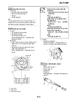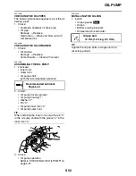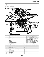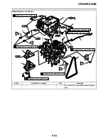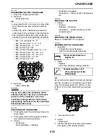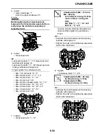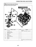
CONNECTING RODS AND PISTONS
5-61
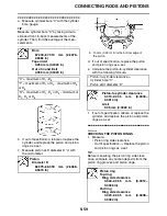
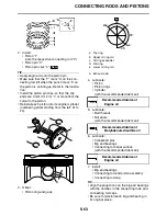
4. Calculate:
• Piston-pin-to-piston-pin-bore clearance
Out of specification
→
Replace the piston
pin and piston as a set.
ET2C01013
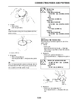
CHECKING THE CONNECTING RODS
1. Measure:
• Crankshaft-pin-to-big-end-bearing clear-
ance
Out of specification
→
Replace the big
end bearings.
▼▼▼▼▼▼▼▼▼▼▼▼▼▼▼▼▼▼▼▼▼▼▼▼▼▼▼▼▼▼
The following procedure applies to all of the
connecting rods.
ECA13930
Do not interchange the big end bearings
and connecting rods. To obtain the correct
crankshaft-pin-to-big-end-bearing clear-
ance and prevent engine damage, the big
end bearings must be installed in their orig-
inal positions.
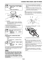
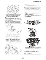
a. Clean the big end bearings, crankshaft
pins, and the inside of the connecting rods
halves.
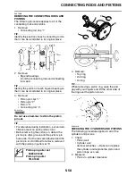
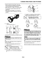
b. Install the big end upper bearing into the
connecting rod and the big end lower bear-
ing into the connecting rod cap.
TIP
Align the projections “a” on the big end bear-
ings with the notches “b” in the connecting rod
and connecting rod cap.
c. Put a piece of Plastigauge
®
“1” on the
crankshaft pin.
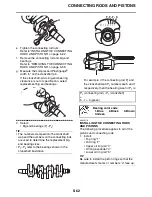
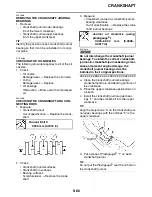
d. Assemble the connecting rod halves.
TIP
• Do not move the connecting rod or crank-
shaft until the clearance measurement has
been completed.
• Lubricate the bolt threads and nut seats with
molybdenum disulfide grease.
• Make sure the “Y” mark “c” on the connecting
rod faces towards the left side of the crank-
shaft.
• Make sure the characters “d” on both the
connecting rod and connecting rod cap are
aligned.
Piston pin bore inside diameter
15.002–15.013 mm (0.5906–
0.5911 in)
Limit
15.043 mm (0.5922 in)
• Piston-pin-to-piston-pin-bore clearance =
Piston pin bore diameter “b” -
Piston pin outside diameter “a”
Piston-pin-to-piston-pin-bore
clearance
0.002–0.022 mm (0.00007–
0.00068 in)
Oil clearance (using plasti-
gauge
®
)
0.037–0.061 mm (0.0015–
0.0024 in)
1
Summary of Contents for R6 2009
Page 1: ...SERVICE MANUAL YZFR6Y C 13S 28197 11 LIT 11616 22 51 2009 ...
Page 6: ......
Page 8: ......
Page 60: ...LUBRICATION SYSTEM CHART AND DIAGRAMS 2 29 EAS20410 LUBRICATION DIAGRAMS 1 2 3 4 ...
Page 62: ...LUBRICATION SYSTEM CHART AND DIAGRAMS 2 31 1 2 3 4 8 7 6 5 ...
Page 64: ...LUBRICATION SYSTEM CHART AND DIAGRAMS 2 33 1 2 3 4 5 ...
Page 66: ...LUBRICATION SYSTEM CHART AND DIAGRAMS 2 35 1 5 4 3 2 ...
Page 68: ...LUBRICATION SYSTEM CHART AND DIAGRAMS 2 37 3 1 2 5 4 ...
Page 70: ...LUBRICATION SYSTEM CHART AND DIAGRAMS 2 39 1 3 2 ...
Page 71: ...LUBRICATION SYSTEM CHART AND DIAGRAMS 2 40 1 Oil pipe 2 Main axle 3 Drive axle ...
Page 72: ...COOLING SYSTEM DIAGRAMS 2 41 EAS20420 COOLING SYSTEM DIAGRAMS 1 2 3 4 ...
Page 74: ...COOLING SYSTEM DIAGRAMS 2 43 A A 2 1 3 4 5 6 7 8 6 13 8 9 15 14 9 10 11 12 ...
Page 76: ...CABLE ROUTING 2 45 EAS20430 CABLE ROUTING ...
Page 78: ...CABLE ROUTING 2 47 ...
Page 80: ...CABLE ROUTING 2 49 ...
Page 82: ...CABLE ROUTING 2 51 ...
Page 84: ...CABLE ROUTING 2 53 ...
Page 86: ...CABLE ROUTING 2 55 ...
Page 88: ...CABLE ROUTING 2 57 ...
Page 90: ...CABLE ROUTING 2 59 A A ...
Page 92: ...CABLE ROUTING 2 61 ...
Page 95: ......
Page 135: ......
Page 206: ...CHAIN DRIVE 4 71 1 2 3 a a New ...
Page 209: ......
Page 240: ...PICKUP ROTOR 5 31 ...
Page 286: ...TRANSMISSION 5 77 ...
Page 300: ...WATER PUMP 6 13 ...
Page 316: ...AIR INDUCTION SYSTEM 7 15 EAS27040 AIR INDUCTION SYSTEM 2 1 2 4 3 4 3 6 4 5 A A ...
Page 323: ......
Page 324: ...IGNITION SYSTEM 8 1 EAS27090 IGNITION SYSTEM EAS27110 CIRCUIT DIAGRAM ...
Page 330: ...ELECTRIC STARTING SYSTEM 8 7 EAS27160 ELECTRIC STARTING SYSTEM EAS27170 CIRCUIT DIAGRAM ...
Page 336: ...CHARGING SYSTEM 8 13 EAS27200 CHARGING SYSTEM EAS27210 CIRCUIT DIAGRAM ...
Page 339: ...CHARGING SYSTEM 8 16 ...
Page 340: ...LIGHTING SYSTEM 8 17 EAS27240 LIGHTING SYSTEM EAS27250 CIRCUIT DIAGRAM ...
Page 344: ...SIGNALING SYSTEM 8 21 EAS27270 SIGNALING SYSTEM EAS27280 CIRCUIT DIAGRAM ...
Page 351: ...SIGNALING SYSTEM 8 28 ...
Page 352: ...COOLING SYSTEM 8 29 EAS27300 COOLING SYSTEM EAS27310 CIRCUIT DIAGRAM ...
Page 355: ...COOLING SYSTEM 8 32 ...
Page 356: ...FUEL INJECTION SYSTEM 8 33 EAS27330 FUEL INJECTION SYSTEM EAS27340 CIRCUIT DIAGRAM ...
Page 395: ...FUEL INJECTION SYSTEM 8 72 ...
Page 396: ...FUEL PUMP SYSTEM 8 73 EAS27550 FUEL PUMP SYSTEM EAS27560 CIRCUIT DIAGRAM ...
Page 399: ...FUEL PUMP SYSTEM 8 76 ...
Page 400: ...ELECTRICAL COMPONENTS 8 77 EAS27970 ELECTRICAL COMPONENTS ...
Page 402: ...ELECTRICAL COMPONENTS 8 79 1 5 4 3 2 6 7 8 9 10 12 13 11 14 15 16 17 18 ...
Page 404: ...ELECTRICAL COMPONENTS 8 81 EAS27980 CHECKING THE SWITCHES ...
Page 431: ......
Page 432: ...YAMAHA MOTOR CO LTD 2500 SHINGAI IWATA SHIZUOKA JAPAN ...

