FUEL INJECTION SYSTEM
8-44
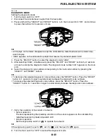
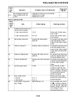
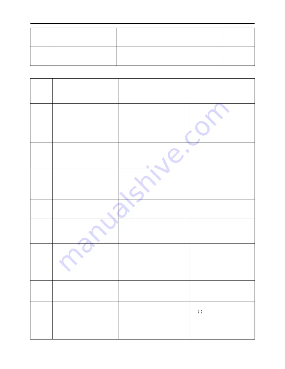
Sensor operation table
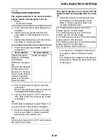
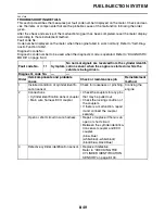
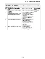
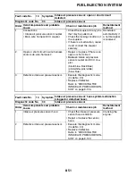
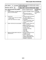
Er-4
Non-registered data has
been received from the
meter.
• Improper connection in wire harness.
• Malfunction in meter.
• Malfunction in ECU.
—
Diag-
nostic
code
No.
Item
Meter display
Checking method
01
Throttle position sensor (for
throttle valves) signal 1
• Fully closed position
12–21
Check with throttle valves
fully closed.
• Fully opened position
97–106
Check with throttle valves
fully opened.
02
Atmospheric pressure
Displays the atmospheric
pressure.
Compare the actually mea-
sured atmospheric pres-
sure with the meter display
value.
03
Intake air pressure
Displays intake air pressure.
Compare the actually mea-
sured atmospheric pres-
sure with the meter display
value without cranking the
engine.
05
Intake air temperature
Displays the intake air tem-
perature.
Compare the actually mea-
sured air temperature with
the meter display value.
06
Coolant temperature
Displays the coolant tempera-
ture.
Compare the actually mea-
sured coolant temperature
with the meter display
value.
07
Vehicle speed pulse
0–999
Check that the number
increases when the rear
wheel is rotated. The num-
ber is cumulative and does
not reset each time the
wheel is stopped.
08
Lean angle sensor
Remove the lean angle
sensor and incline it more
than 65 degrees.
• Upright
0.4–1.4
• Overturned
3.7–4.4
09
Fuel system voltage (bat-
tery voltage)
Approximately 12.0
Set the engine stop switch
to “
”, and then compare
with the actually measured
battery voltage. (If the bat-
tery voltage is lower,
recharge the battery.)
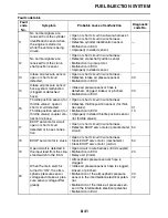
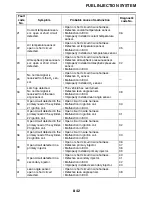
Fault
code
No.
Symptom
Probable cause of malfunction
Diagnostic
code No.
Summary of Contents for R6 2009
Page 1: ...SERVICE MANUAL YZFR6Y C 13S 28197 11 LIT 11616 22 51 2009 ...
Page 6: ......
Page 8: ......
Page 60: ...LUBRICATION SYSTEM CHART AND DIAGRAMS 2 29 EAS20410 LUBRICATION DIAGRAMS 1 2 3 4 ...
Page 62: ...LUBRICATION SYSTEM CHART AND DIAGRAMS 2 31 1 2 3 4 8 7 6 5 ...
Page 64: ...LUBRICATION SYSTEM CHART AND DIAGRAMS 2 33 1 2 3 4 5 ...
Page 66: ...LUBRICATION SYSTEM CHART AND DIAGRAMS 2 35 1 5 4 3 2 ...
Page 68: ...LUBRICATION SYSTEM CHART AND DIAGRAMS 2 37 3 1 2 5 4 ...
Page 70: ...LUBRICATION SYSTEM CHART AND DIAGRAMS 2 39 1 3 2 ...
Page 71: ...LUBRICATION SYSTEM CHART AND DIAGRAMS 2 40 1 Oil pipe 2 Main axle 3 Drive axle ...
Page 72: ...COOLING SYSTEM DIAGRAMS 2 41 EAS20420 COOLING SYSTEM DIAGRAMS 1 2 3 4 ...
Page 74: ...COOLING SYSTEM DIAGRAMS 2 43 A A 2 1 3 4 5 6 7 8 6 13 8 9 15 14 9 10 11 12 ...
Page 76: ...CABLE ROUTING 2 45 EAS20430 CABLE ROUTING ...
Page 78: ...CABLE ROUTING 2 47 ...
Page 80: ...CABLE ROUTING 2 49 ...
Page 82: ...CABLE ROUTING 2 51 ...
Page 84: ...CABLE ROUTING 2 53 ...
Page 86: ...CABLE ROUTING 2 55 ...
Page 88: ...CABLE ROUTING 2 57 ...
Page 90: ...CABLE ROUTING 2 59 A A ...
Page 92: ...CABLE ROUTING 2 61 ...
Page 95: ......
Page 135: ......
Page 206: ...CHAIN DRIVE 4 71 1 2 3 a a New ...
Page 209: ......
Page 240: ...PICKUP ROTOR 5 31 ...
Page 286: ...TRANSMISSION 5 77 ...
Page 300: ...WATER PUMP 6 13 ...
Page 316: ...AIR INDUCTION SYSTEM 7 15 EAS27040 AIR INDUCTION SYSTEM 2 1 2 4 3 4 3 6 4 5 A A ...
Page 323: ......
Page 324: ...IGNITION SYSTEM 8 1 EAS27090 IGNITION SYSTEM EAS27110 CIRCUIT DIAGRAM ...
Page 330: ...ELECTRIC STARTING SYSTEM 8 7 EAS27160 ELECTRIC STARTING SYSTEM EAS27170 CIRCUIT DIAGRAM ...
Page 336: ...CHARGING SYSTEM 8 13 EAS27200 CHARGING SYSTEM EAS27210 CIRCUIT DIAGRAM ...
Page 339: ...CHARGING SYSTEM 8 16 ...
Page 340: ...LIGHTING SYSTEM 8 17 EAS27240 LIGHTING SYSTEM EAS27250 CIRCUIT DIAGRAM ...
Page 344: ...SIGNALING SYSTEM 8 21 EAS27270 SIGNALING SYSTEM EAS27280 CIRCUIT DIAGRAM ...
Page 351: ...SIGNALING SYSTEM 8 28 ...
Page 352: ...COOLING SYSTEM 8 29 EAS27300 COOLING SYSTEM EAS27310 CIRCUIT DIAGRAM ...
Page 355: ...COOLING SYSTEM 8 32 ...
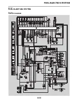
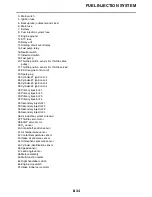
Page 356: ...FUEL INJECTION SYSTEM 8 33 EAS27330 FUEL INJECTION SYSTEM EAS27340 CIRCUIT DIAGRAM ...
Page 395: ...FUEL INJECTION SYSTEM 8 72 ...
Page 396: ...FUEL PUMP SYSTEM 8 73 EAS27550 FUEL PUMP SYSTEM EAS27560 CIRCUIT DIAGRAM ...
Page 399: ...FUEL PUMP SYSTEM 8 76 ...
Page 400: ...ELECTRICAL COMPONENTS 8 77 EAS27970 ELECTRICAL COMPONENTS ...
Page 402: ...ELECTRICAL COMPONENTS 8 79 1 5 4 3 2 6 7 8 9 10 12 13 11 14 15 16 17 18 ...
Page 404: ...ELECTRICAL COMPONENTS 8 81 EAS27980 CHECKING THE SWITCHES ...
Page 431: ......
Page 432: ...YAMAHA MOTOR CO LTD 2500 SHINGAI IWATA SHIZUOKA JAPAN ...

