CABLE ROUTING
2-50
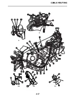
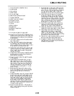
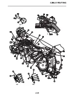
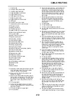
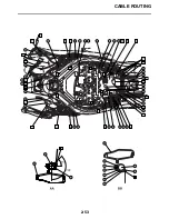
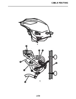
1. Main switch lead
2. Left handlebar switch lead
3. Left radiator fan motor lead
4. Sidestand bracket cover
5. AC magneto lead
6. Crankcase
7. Drive sprocket cover
8. Fuel tank breather hose
9. Fuel tank drain hose
10.Drive chain guide
11.Sidestand switch lead
12.Oil level switch lead
13.Oil filter
A. 45–55 mm (1.77–2.17 in)
B. Bend the main harness as shown in the
illustration.
C. Route the plastic locking tie through the
hole of the rectifier/regulator bracket and
fasten the main harness. Face the end of
the plastic locking tie outward. Cut off the
excess end of the plastic locking tie to 1–5
mm (0.04–0.20 in).
D. Route the left radiator fan motor lead from
where engine is suspended to under the
main harness.
E. Route the starter motor lead, speed sensor
lead, sidestand switch lead and oil level
switch lead between the clamp and crank-
case shift boss. When routing, set the
starter motor lead outside. There is no
order for placing other leads.
F. The clamp on the fuel tank drain hose and
fuel tank breather hose should be below
the engine clamp.
G. 30–50 mm (1.18–1.97 in)
H. Route the fuel tank drain hose and fuel
tank breather hose through the guide of the
sidestand bracket cover. Route the side-
stand switch lead from between the guides
to inside of the hose.
I. Route the AC magneto lead between the
frame and throttle body and under the
hose.
J. After connecting the connector of the AC
magneto lead, put a cover on.
K. To the front left turn signal light.
L. Route the plastic locking tie through the
hole of the rectifier/regulator bracket and
fasten the main harness. Face the end of
the plastic locking tie outward. Cut off the
excess end of the plastic locking tie to 1–5
mm (0.04–0.20 in).
M. There is no order of setting which harness
front or back.
N. Fold back the radiator fan motor lead (main
harness side) toward back of the vehicle as
shown in the illustration and insert it into
the left coupler holder. The folded part can
be either outside or inside of the radiator
fan motor lead coupler.
O. Route the AC magneto lead under the left
radiator fan motor lead.
P. Fasten the left handle bar switch lead with
a plastic locking tie, making sure the left
handle bar switch lead is positioned as
shown in the illustration.
Q. Inside
R. Outside
S. For U49 and California, the coupler is with-
out a bullet terminal, so insertion is unnec-
essary. Connection point should be the
same as for Europe (position shown in this
illustration) (this coupler does not exist for
Canada).
T. Couplers to fasten onto the bracket are
handlebar switch lead, main switch lead
and radiator fan motor lead.
Summary of Contents for R6 2009
Page 1: ...SERVICE MANUAL YZFR6Y C 13S 28197 11 LIT 11616 22 51 2009 ...
Page 6: ......
Page 8: ......
Page 60: ...LUBRICATION SYSTEM CHART AND DIAGRAMS 2 29 EAS20410 LUBRICATION DIAGRAMS 1 2 3 4 ...
Page 62: ...LUBRICATION SYSTEM CHART AND DIAGRAMS 2 31 1 2 3 4 8 7 6 5 ...
Page 64: ...LUBRICATION SYSTEM CHART AND DIAGRAMS 2 33 1 2 3 4 5 ...
Page 66: ...LUBRICATION SYSTEM CHART AND DIAGRAMS 2 35 1 5 4 3 2 ...
Page 68: ...LUBRICATION SYSTEM CHART AND DIAGRAMS 2 37 3 1 2 5 4 ...
Page 70: ...LUBRICATION SYSTEM CHART AND DIAGRAMS 2 39 1 3 2 ...
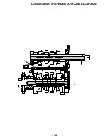
Page 71: ...LUBRICATION SYSTEM CHART AND DIAGRAMS 2 40 1 Oil pipe 2 Main axle 3 Drive axle ...
Page 72: ...COOLING SYSTEM DIAGRAMS 2 41 EAS20420 COOLING SYSTEM DIAGRAMS 1 2 3 4 ...
Page 74: ...COOLING SYSTEM DIAGRAMS 2 43 A A 2 1 3 4 5 6 7 8 6 13 8 9 15 14 9 10 11 12 ...
Page 76: ...CABLE ROUTING 2 45 EAS20430 CABLE ROUTING ...
Page 78: ...CABLE ROUTING 2 47 ...
Page 80: ...CABLE ROUTING 2 49 ...
Page 82: ...CABLE ROUTING 2 51 ...
Page 84: ...CABLE ROUTING 2 53 ...
Page 86: ...CABLE ROUTING 2 55 ...
Page 88: ...CABLE ROUTING 2 57 ...
Page 90: ...CABLE ROUTING 2 59 A A ...
Page 92: ...CABLE ROUTING 2 61 ...
Page 95: ......
Page 135: ......
Page 206: ...CHAIN DRIVE 4 71 1 2 3 a a New ...
Page 209: ......
Page 240: ...PICKUP ROTOR 5 31 ...
Page 286: ...TRANSMISSION 5 77 ...
Page 300: ...WATER PUMP 6 13 ...
Page 316: ...AIR INDUCTION SYSTEM 7 15 EAS27040 AIR INDUCTION SYSTEM 2 1 2 4 3 4 3 6 4 5 A A ...
Page 323: ......
Page 324: ...IGNITION SYSTEM 8 1 EAS27090 IGNITION SYSTEM EAS27110 CIRCUIT DIAGRAM ...
Page 330: ...ELECTRIC STARTING SYSTEM 8 7 EAS27160 ELECTRIC STARTING SYSTEM EAS27170 CIRCUIT DIAGRAM ...
Page 336: ...CHARGING SYSTEM 8 13 EAS27200 CHARGING SYSTEM EAS27210 CIRCUIT DIAGRAM ...
Page 339: ...CHARGING SYSTEM 8 16 ...
Page 340: ...LIGHTING SYSTEM 8 17 EAS27240 LIGHTING SYSTEM EAS27250 CIRCUIT DIAGRAM ...
Page 344: ...SIGNALING SYSTEM 8 21 EAS27270 SIGNALING SYSTEM EAS27280 CIRCUIT DIAGRAM ...
Page 351: ...SIGNALING SYSTEM 8 28 ...
Page 352: ...COOLING SYSTEM 8 29 EAS27300 COOLING SYSTEM EAS27310 CIRCUIT DIAGRAM ...
Page 355: ...COOLING SYSTEM 8 32 ...
Page 356: ...FUEL INJECTION SYSTEM 8 33 EAS27330 FUEL INJECTION SYSTEM EAS27340 CIRCUIT DIAGRAM ...
Page 395: ...FUEL INJECTION SYSTEM 8 72 ...
Page 396: ...FUEL PUMP SYSTEM 8 73 EAS27550 FUEL PUMP SYSTEM EAS27560 CIRCUIT DIAGRAM ...
Page 399: ...FUEL PUMP SYSTEM 8 76 ...
Page 400: ...ELECTRICAL COMPONENTS 8 77 EAS27970 ELECTRICAL COMPONENTS ...
Page 402: ...ELECTRICAL COMPONENTS 8 79 1 5 4 3 2 6 7 8 9 10 12 13 11 14 15 16 17 18 ...
Page 404: ...ELECTRICAL COMPONENTS 8 81 EAS27980 CHECKING THE SWITCHES ...
Page 431: ......
Page 432: ...YAMAHA MOTOR CO LTD 2500 SHINGAI IWATA SHIZUOKA JAPAN ...

