background image

– 42 –

ENG

ENGINE

ENGINE REMOVAL

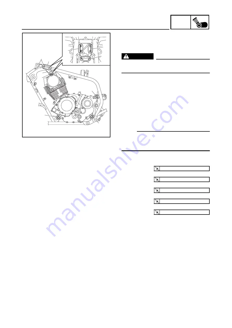
INSTALLING THE ENGINE

WARNING

Securely support the machine so there is
no danger of it falling over.

1. Install:

• engine assembly

2. Install:

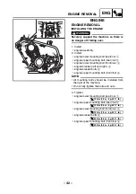
• engine lower mounting bolt (rear)/nut 

1

• engine upper mounting bolt (rear)/nut 

2

• engine lower mounting bolt (front)/nut 

3

• engine bracket (left and right) 

4

• engine bracket bolts 

5

• engine upper mounting bolt (front)/nut 

6

NOTE:

• All mounting bolts should be installed from

the right of the machine.

• Do not fully tighten the bolts and nuts.

3. Tighten:

• engine lower mounting bolt (rear)/nut 

1

• engine upper mounting bolt (rear)/nut 

2

• engine lower mounting bolt (front)/nut 

3

• engine bracket bolts 

5

• engine upper mounting bolt (front)/nut 

6

5

6

5

1

3

2

4

6

5

T


R

.

.

73 Nm (7.3 m · kg, 53 ft · lb)

T


R

.

.

73 Nm (7.3 m · kg, 53 ft · lb)

T


R

.

.

73 Nm (7.3 m · kg, 53 ft · lb)

T


R

.

.

33 Nm (3.3 m · kg, 24 ft · lb)

T


R

.

.

33 Nm (3.3 m · kg, 24 ft · lb)

ENGINE REMOVAL

Summary of Contents for Raptor YFM350S

Page 1: ...YFM350S3GD AE7 SUPPLEMENTARY SERVICE MANUAL ...

Page 2: ......

Page 3: ...is Supplementary Service Manual together with the following manual YFM350X J 97 SERVICE MANUAL 3GD AE5 YFM350X P 2002 SUPPLEMENTARY SERVICE MANUAL 3GD AE6 YFM350S SUPPLEMENTARY SERVICE MANUAL 2004 by Yamaha Motor Co Ltd First edition January 2004 All rights reserved Any reproduction or unauthorized use without the written permission of Yamaha Motor Co Ltd is expressly prohibited ...

Page 4: ...ions and sig nificant changes in specifications or procedures will be forwarded to all authorized Yamaha dealers and will appear in future editions of this manual where applicable NOTE _ Designs and specifications are subject to change without notice EBS00003 IMPORTANT INFORMATION Particularly important information is distinguished in this manual by the following notations The Safety Alert Symbol ...

Page 5: ...parts and clarify procedure steps there are exploded diagrams at the start of each removal and disassembly section 1 An easy to see exploded diagram 4 is provided for removal and disassembly jobs 2 Numbers 5 are given in the order of the jobs in the exploded diagram A number that is enclosed by a circle indicates a disassembly step 3 An explanation of jobs and notes is presented in an easy to read...

Page 6: ...arance D Engine speed E Ω V A Illustrated symbols F to L in the exploded diagrams indicate the types of lubricants and lubrication points F Apply engine oil G Apply gear oil H Apply molybdenum disulfide oil I Apply wheel bearing grease J Apply lightweight lithium soap base grease K Apply molybdenum disulfide grease L Apply silicon grease Illustrated symbols M to N in the exploded diagrams indicate...

Page 7: ...ANK 25 SEAT SIDE COVERS AND FRONT PANEL 25 FOOT PROTECTORS ENGINE SKID PLATE AND FRONT BUMPER 26 HEADLIGHTS AND FRONT FENDER 27 REAR FENDER 28 FUEL TANK 30 CHASSIS 32 CHECKING THE FRONT BRAKE PADS 32 ADJUSTING THE PARKING BRAKE 32 ADJUSTING THE REAR SHOCK ABSORBER 33 ELECTRICAL SYSTEM 35 CHECKING AND CHARGING THE BATTERY 35 ADJUSTING THE HEADLIGHT BEAMS 40 REPLACING A HEADLIGHT BULB 41 ENGINE 42 E...

Page 8: ... FRONT ARMS AND FRONT SHOCK ABSORBER 51 REAR BRAKE 53 ASSEMBLING THE REAR BRAKE CALIPER 53 REAR SHOCK ABSORBER AND SWINGARM 54 HANDLING THE REAR SHOCK ABSORBER AND GAS CYLINDER 56 DISPOSING OF THE REAR SHOCK ABSORBER AND GAS CYLINDER 56 ELECTRICAL 57 ELECTRICAL COMPONENTS 57 YFM350S WIRING DIAGRAM ...

Page 9: ... 1 GEN INFO GENERAL INFORMATION MACHINE IDENTIFICATION MODEL LABEL The model label 1 is affixed to the frame This information will be needed to order spare parts MACHINE IDENTIFICATION ...

Page 10: ...ffer by shape and part number from country to country In such a case two types are provided When placing an order refer to the list provided below to avoid any mistakes For US and CDN P N YM YU YS YK ACC Except for US and CDN P N 90890 Tool No Tool name How to use Illustration 90890 01443 YU 33975 Steering nut wrench This tool is needed to loosen and tighten the rear shock absorber locknut 90890 0...

Page 11: ...nder arrangement Forward inclined single cylinder Displacement 349 0 cm3 21 30 cu in Bore stroke 83 0 64 5 mm 3 27 2 54 in Compression ratio 9 20 1 Compression pressure 850 kPa 8 5 kg cm2 120 9 psi at 350 r min Starting system Electric starter Oil capacity Engine oil Periodic oil change 2 50 L 2 20 Imp qt 2 64 US qt With oil filter replacement 2 60 L 2 29 Imp qt 2 75 US qt Total amount 3 20 L 2 82...

Page 12: ...16 33 10 6 806 Chassis Frame type Steel tube frame Caster angle 6 Trail 26 0 mm 1 02 in Toe in unloaded 20 30 mm 0 79 1 18 in Tires Type Tubeless Size front AT21 7 10 rear AT20 10 9 Manufacturer front DUNLOP rear DUNLOP Type front KT851B rear KT877A Brakes Front brake type Dual disc brake operation Right hand operation Rear brake type Single disc brake operation Right foot operation Electrical Ign...

Page 13: ... 5YT1 00 Main jet M J 142 5 Main air jet M A J 35 Jet needle J N 5JFC39 2 Needle jet N J P 0M Pilot jet P J 22 5 Pilot air jet P A J 1 65 P A J 2 165 Pilot outlet P O 1 Bypass 1 B P 1 0 8 Bypass 2 B P 2 0 8 Bypass 3 B P 3 0 8 Pilot screw turns out P S 2 1 4 For CDN Europe and Oceania Valve seat V S 2 5 Starter jet G S 70 Throttle valve size Th V 105 Fuel level F L 4 5 mm 0 16 0 20 in Above the flo...

Page 14: ...e holder Bolt M8 1 16 1 6 11 Right crankcase cover Bolt M6 15 10 1 0 7 2 Left crankcase cover Bolt M6 9 11 1 1 8 0 Crankshaft end cover Bolt M6 4 7 0 7 5 1 Bearing retainer balancer shaft Screw M6 2 7 0 7 5 1 Bearing retainer main axle Screw M6 2 7 0 7 5 1 Bearing retainer left crankcase Screw M5 2 7 0 7 5 1 Drive sprocket Nut M20 1 90 9 0 65 Use a lock washer Stopper lever Bolt M6 1 10 1 0 7 2 Re...

Page 15: ...1 kg mm 325 46 lb in Stroke 0 88 0 mm 0 3 46 in Enclosed gas pressure standard 1 500 kPa 15 0 kg cm2 213 3 psi Min 1 450 kPa 14 5 kg cm2 206 2 psi Max 1 550 kPa 15 5 kg cm2 220 4 psi Wheel Front wheel type Panel wheel Rear wheel type Panel wheel Front rim size material 10 5 5 AT Aluminum Rear rim size material 9 8 5 AT Aluminum Rim runout limit Vertical 2 0 mm 0 08 in Lateral 2 0 mm 0 08 in Front ...

Page 16: ...ng brake lever assembly M5 4 0 4 2 9 Front brake hose and upper front arm M6 7 0 7 5 1 Front brake pipe and brake pipe joint M10 19 1 9 13 Brake pipe joint and frame M6 10 1 0 7 2 Brake caliper bleed screw M8 6 0 6 4 3 Rear brake hose union bolt M10 28 2 8 20 Parking brake adjusting bolt and locknut M8 16 1 6 11 Rear brake light switch bracket and frame M6 7 0 7 5 1 Rear brake master cylinder and ...

Page 17: ...et M6 7 0 7 5 1 Front fender and frame M6 7 0 7 5 1 Front fender bracket center and frame M6 10 1 0 7 2 Front fender brackets left and right and frame M6 13 1 3 9 4 Headlight bracket and front fender bracket M6 7 0 7 5 1 Rear fender and frame M6 10 1 0 7 2 Rear fender and rear bumper M6 7 0 7 5 1 Rear fender and rear fender stay M6 7 0 7 5 1 Rear fender stay and frame M6 7 0 7 5 1 Rear fender stay...

Page 18: ...ort circuit Model manufacturer SH640E 11 SHINDENGEN No load regulated voltage 14 1 14 9 V Rectifier capacity 14 A Withstand voltage 200 V Starter relay Model manufacturer 2768095 A JIDECO Amperage rating 180 A Coil winding resistance 4 18 4 62 Ω Battery Specific gravity 1 310 at 20 C 68 F Starter motor Model manufacturer DBQD5 DENSO Output 0 7 kW Armature coil resistance 0 0118 0 0133 Ω at 20 C 68...

Page 19: ...lead 7 Throttle cable 8 Neutral indicator light 9 Reverse indicator light 0 Handlebar switch lead È Fasten the front brake light switch lead with two plastic bands É Fasten the starter cable clutch switch lead and handlebar switch lead with a plastic band Ê Fasten the clutch switch lead and handlebar switch lead with a plastic band 6 5 7 0 1 3 4 8 È 9 2 É Ê ...

Page 20: ...light switch lead 9 Front brake hose 0 Throttle cable È Pass the clutch switch lead handlebar switch lead neutral reverse indicator light lead front brake light switch lead and starter cable through the guide É Fasten the clutch switch lead handlebar switch lead neutral reverse indicator light lead and front brake light switch lead securely with a plas tic locking tie 1 2 3 4 5 6 0 9 8 È É Ë 7 Ê ...

Page 21: ... switch lead neutral reverse indicator light lead and front brake light switch lead in front of the guide Ë Pass the throttle cable clutch cable and parking brake cable to the right side of the steering shaft 1 2 3 4 5 6 0 9 8 È É Ë 7 Ê CABLE ROUTING ...

Page 22: ... hose 7 Carburetor air vent hose 8 Crankcase breather hose 9 Reverse switch lead 0 Negative battery lead A Carburetor overflow hose B Neutral switch lead C Starter motor lead D Clutch cable E Parking brake cable A A B B C C D D Ñ Ê Ò Ó Ô É C 4 3 5 1 2 7 3 3 4 4 3 C C C Ï Ì Í Î E D C Ð B A 0 9 È Ë 4 4 6 7 8 3 A A B B C C D D ...

Page 23: ...le between the carburetor overflow hose and crankcase breather hose Ì Fasten the A C magneto lead neutral switch lead reverse switch lead and negative battery lead with a plastic band Face the end of the plastic band inward Í Pass the neutral switch lead and carburetor overflow hose through the guide on the drive sprocket cover Route the neutral switch lead behind the carburetor overflow hose Î Fa...

Page 24: ...end of the plastic band down Ò Pass a plastic band through the hole in the fuel tank shield and then fasten the wire harness starter motor lead and starter cable with the plastic band The end of the plastic band should be under the frame facing inward Ó Route the wire harness and starter motor lead above the starter cable Ô Fasten the wire harness and starter motor lead with a plastic band Face th...

Page 25: ...egative battery lead 7 Carburetor air vent hose 8 Positive battery lead 9 Starter relay 0 Starting circuit cut off relay È Pass the wire harness negative battery lead and starter motor lead through the hole in the rear fender É More than 15 mm 0 6 in B C A A B C 9 1 8 5 5 6 7 2 1 3 4 7 4 6 0 3 B B A A C C È É ...

Page 26: ...tor A Parking brake cable B Rear brake light switch C Rear brake light switch lead D Drive select lever switch connector È Route the rear brake light switch lead over the parking brake cable É Pass the parking brake cable through the cable guides Ê Fasten the drive select lever switch lead with a plastic band Face the end of the plastic band inward A C È Ê 1 2 5 6 7 8 3 9 0 A B 4 Ì Í Ñ 3 D Ò Î Ð Ï...

Page 27: ...e headlight Ï Route the starter motor lead in front of the front fender bracket Ð Pass the starter motor lead through the guide Ñ Fasten the rear brake light switch lead under the frame with two plastic bands Face the end of each band rearward Ò Pass a plastic band through the holes in the fuel tank shield and then fasten the throttle cable and drive select lever switch connector with the plastic ...

Page 28: ... cable 7 Starter motor lead 8 Wire harness 9 Starter cable 0 Rectifier regulator È Fasten the wire harness with the holder É Route the headlight lead over the frame Ê Fasten the main switch lead with the holder on the front fender Ë Pass the main switch lead through the guide on the front fender 1 3 4 5 6 È 2É Ê 3Ë A A 0 È 2É 9 8 7 A A ...

Page 29: ...rness 9 Starter motor lead È Fasten the wire harness by inserting the projec tions on the plastic tab into the hole in the rear fender É Pass the tail brake light lead through the guide on the rear fender Ê Fasten the tail brake light lead with the holders on the rear fender Ë Route the tail brake light lead under the battery holding bracket 9 1 2 3 4 8 7 5Ë 6Ì Í È É É Ê Ê Ê ...

Page 30: ...Ì Connect the end of the negative battery lead with the gray tape to the negative battery termi nal Í Cover the positive battery lead terminal and starter motor lead terminal with the covers 9 1 2 3 4 8 7 5Ë 6Ì Í È É É Ê Ê Ê ...

Page 31: ... operation Adjust engine idling speed Crankcase breather system Check breather hose for cracks or damage Replace if necessary Exhaust system Check for leakage Tighten if necessary Replace gasket s if necessary Fuel line Check fuel hose for cracks or damage Replace if necessary Engine oil Replace Warm engine before draining Engine oil filter ele ment Clean Replace if necessary Engine oil strainer C...

Page 32: ...k the brake fluid level and add fluid as required On the inner parts of the master cylinders and calipers replace the oil seals every two years Replace the brake hoses every four years or if cracked or damaged WARNING Indicates a potential hazard that could result in serious injury or death Fittings and fasten ers Check all chassis fittings and fasteners Correct if necessary Lights and switches Ch...

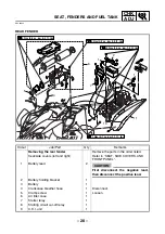
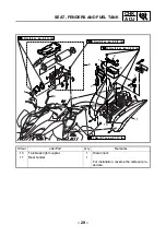
Page 33: ...L 1 2 3 4 Order Job Part Q ty Remarks Removing the seat side covers and front panel Remove the parts in the order listed 1 Seat 1 NOTE _ Pull back the seat lock lever than pull up on the rear of the seat 2 Left side cover 1 3 Right side cover 1 4 Front panel 1 For installation reverse the removal pro cedure ...

Page 34: ... 7 m kg 12 ft Ib T R 12 Nm 1 2 m kg 8 7 ft Ib T R 12 Nm 1 2 m kg 8 7 ft Ib 1 3 Order Job Part Q ty Remarks Removing the foot protectors engine skid plate and front bumper Remove the parts in the order listed 1 Left foot protector 1 2 Right foot protector 1 3 Engine skid plate 1 4 Front bumper 1 For installation reverse the removal pro cedure ...

Page 35: ... ft Ib 2 3 1 1 5 4 Order Job Part Q ty Remarks Removing the headlights and front fender Remove the parts in the order listed Seat side covers left and right front panel Refer to SEAT SIDE COVERS AND FRONT PANEL 1 Headlight coupler 2 Disconnect 2 Left headlight 1 3 Right headlight 1 4 Main switch coupler 1 Disconnect 5 Front fender 1 For installation reverse the removal pro cedure ...

Page 36: ...rks Removing the rear fender Remove the parts in the order listed Seat side covers left and right Refer to SEAT SIDE COVERS AND FRONT PANEL 1 Battery lead 2 CAUTION _ First disconnect the negative lead then disconnect the positive lead 2 Battery holding bracket 1 3 Battery 1 4 Crankcase breather hose 1 Disconnect 5 Clamp screw 1 Loosen 6 Air filter case 1 7 Starter relay 1 8 Starting circuit cut o...

Page 37: ...kg 7 2 ft Ib T R 7 Nm 0 7 m kg 5 1 ft Ib T R 3 Nm 0 3 m kg 2 2 ft Ib T R 3 Nm 0 3 m kg 2 2 ft Ib 6 2 3 1 11 8 7 9 1 4 5 10 Order Job Part Q ty Remarks 10 Tail brake light coupler 1 Disconnect 11 Rear fender 1 For installation reverse the removal pro cedure ...

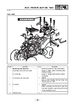
Page 38: ...der listed Seat side covers left and right Refer to SEAT SIDE COVERS AND FRONT PANEL Front fender Refer to HEADLIGHTS AND FRONT FENDER 1 Fuel hose fuel cock side 1 NOTE _ Before disconnecting the fuel hose turn the fuel cock to OFF 2 Fuel tank 1 NOTE _ When installing the fuel tank pass the fuel tank breather hose through the hole in the handlebar cover 3 Plastic band 2 ...

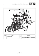
Page 39: ... 31 CHK ADJ SEAT FENDERS AND FUEL TANK T R 7 Nm 0 7 m kg 5 1 ft Ib 3 4 2 1 Order Job Part Q ty Remarks 4 Fuel tank shield 1 For installation reverse the removal pro cedure ...

Page 40: ...in chapter 6 Manual No 3GD AE5 ADJUSTING THE PARKING BRAKE 1 Check parking brake cable end length a Out of specification Adjust 2 Adjust parking brake cable end length a Loosen the locknut 1 and adjusting bolt 2 b Slide back the rubber cover c Loosen the locknut 3 d Turn the adjusting nut 4 in direction b or c until the specified brake cable end length is obtained e Tighten the locknut 3 f Slowly ...

Page 41: ...ve steps again EBS00111 ADJUSTING THE REAR SHOCK ABSORBER 1 Remove seat Refer to SEAT SIDE COVERS AND FRONT PANEL 2 Remove air filter case Refer to REAR FENDER 3 Adjust spring preload a Elevate the rear wheels by placing a suit able stand under the frame b Loosen the locknut 1 c Turn the adjusting ring 2 in direction a or b Direction a Spring preload is increased suspension is harder Direction b S...

Page 42: ...ximum or minimum setting d Tighten the locknut 1 with a steering nut wrench 3 NOTE Set the torque wrench at a right angle to the steering nut wrench NOTE _ Always tighten the locknut against the adjust ing ring then torque it to specification 4 Install air filter case Refer to REAR FENDER 5 Install seat Refer to SEAT SIDE COVERS AND FRONT PANEL Steering nut wrench P N 90890 01443 YU 33975 T R Lock...

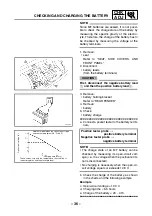
Page 43: ...te as it can cause severe burns or permanent eye injury FIRST AID IN CASE OF BODILY CONTACT EXTERNAL Skin Wash with water Eyes Flush with water for 15 minutes and get immediate medical attention INTERNAL Drink large quantities of water or milk fol lowed with milk of magnesia beaten egg or vegetable oil Get immediate medical attention CAUTION _ This is a sealed battery Never remove the sealing caps...

Page 44: ...charge a Connect a pocket tester to the battery termi nals NOTE _ The charge state of an MF battery can be checked by measuring its open circuit volt age i e the voltage when the positive termi nal is disconnected No charging is necessary when the open cir cuit voltage equals or exceeds 12 8 V b Check the charge of the battery as shown in the charts and the following example Example c Open circuit...

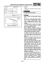
Page 45: ...nected to the battery Before removing the battery charger lead clips from the battery terminals be sure to turn off the battery charger Make sure the battery charger lead clips are in full contact with the battery termi nal and that they are not shorted A cor roded battery charger lead clip may generate heat in the contact area and a weak clip spring may cause sparks If the battery becomes hot to ...

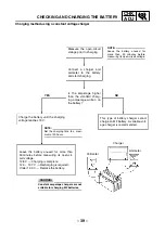
Page 46: ...THE BATTERY If the amperage does not exceed the standard charging amperage after 5 minutes replace the battery If the required charging time exceeds 5 hours it is advisable to check the charging amperage after 5 hours If there is any change in the amperage readjust the voltage to obtain the standard charging amperage Leave the battery unused for more than 30 minutes before measuring its open circu...

Page 47: ...ge the battery until the charging voltage reaches 15 V This type of battery charger cannot charge an MF battery A variable volt age charger is recommended Leave the battery unused for more than 30 minutes before measuring its open cir cuit voltage 12 8 V Charging is complete 12 0 12 7 V Recharging is required Under 12 0 V Replace the battery Constant amperage chargers are not suitable for charging...

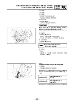
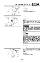
Page 48: ...and then the negative battery lead 2 10 Check battery terminals Dirt Clean with a wire brush Loose connection Connect properly 11 Lubricate battery terminals 12 Install seat Refer to SEAT SIDE COVERS AND FRONT PANEL Recommended lubricant Dielectric grease EBS00122 ADJUSTING THE HEADLIGHT BEAMS 1 Adjust headlight beam vertically a Turn the adjusting bolt 1 in direction a or b Direction a Headlight ...

Page 49: ... it is on since it will be hot Do not touch the bulb until it cools down 4 Install bulb CAUTION _ Avoid touching the glass part of the bulb Keep it free from oil otherwise the trans parency of the glass life of the bulb and luminous flux will be adversely affected If oil gets on the bulb thoroughly clean it with a cloth moistened with alcohol or lac quer thinner 5 Install bulb holder headlight bul...

Page 50: ...cket bolts 5 engine upper mounting bolt front nut 6 NOTE All mounting bolts should be installed from the right of the machine Do not fully tighten the bolts and nuts 3 Tighten engine lower mounting bolt rear nut 1 engine upper mounting bolt rear nut 2 engine lower mounting bolt front nut 3 engine bracket bolts 5 engine upper mounting bolt front nut 6 5 6 5 1 3 2 4 6 5 T R 73 Nm 7 3 m kg 53 ft lb T...

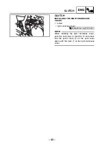
Page 51: ...OVER 1 Install right crankcase cover NOTE When installing the right crankcase cover push the push lever in direction a and check that the punch mark b on the push lever aligns with the mark c on the right crankcase cover b c a T R 10 Nm 1 0 m kg 7 2 ft lb ...

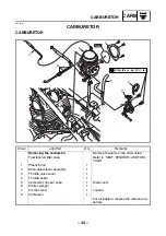
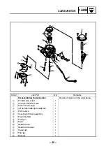
Page 52: ...ove the parts in the order listed Fuel tank air filter case Refer to SEAT FENDERS AND FUEL TANK 1 Plastic band 1 2 Drive select lever assembly 1 3 Throttle valve cover 1 4 Throttle cable 1 5 Carburetor air vent hose 1 Disconnect 6 Starter plunger 1 7 Clamp screw 1 Loosen 8 Carburetor 1 For installation reverse the removal pro cedure CARBURETOR ...

Page 53: ...emove the parts in the order below 1 Throttle stop screw 1 2 Vacuum chamber cover 1 3 Piston valve spring 1 4 Jet needle holder jet needle set 1 5 Piston valve 1 6 Coasting enricher assembly 1 7 Float chamber 1 8 Float pin 1 9 Float 1 0 Needle valve 1 A Needle valve seat 1 B Starter jet 1 C Pilot jet 1 D Main jet 1 ...

Page 54: ... 46 CARB CARBURETOR 9 0 A 8 7 1 D E F H B 6 C G 5 4 3 2 Order Job Part Q ty Remarks E Main jet holder 1 F Needle jet 1 G Pilot air jet 1 H Pilot screw 1 For assembly reverse the disassembly procedure ...

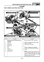
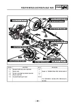
Page 55: ...14 8 7 9 12 14 8 7 13 1 2 4 4 4 4 3 New New LT LT LS LS Order Job Part Q ty Remarks Removing the rear wheels and rear axle hub Remove the parts in the order listed 1 Cotter pin 2 Refer to REAR WHEEL AND WHEEL HUB in chapter 6 Manual No 3GD AE5 2 Axle nut 2 3 Rear wheel 2 4 Wheel hub 2 5 Bolt 2 Refer to REMOVING THE REAR AXLE and INSTALLING THE REAR AXLE 6 Nut 1 7 Locknut 2 8 Adjusting bolt 2 9 Bra...

Page 56: ... R 34 Nm 3 4 m kg 24 ft Ib T R 55 Nm 5 5 m kg 40 ft Ib T R 73 Nm 7 3 m kg 53 ft lb T R 45 Nm 4 5 m kg 32 ft Ib LT LT 6 3 1 2 11 5 5 4 4 10 14 8 7 9 12 14 8 7 13 1 2 4 4 4 4 3 New New LT LT LS LS Order Job Part Q ty Remarks 10 Brake disc brake disc bracket 1 1 11 Rear axle 1 Refer to REMOVING THE REAR AXLE 12 Driven sprocket sprocket bracket 1 1 13 Rear axle hub 1 14 Spacer bearing oil seal 1 2 2 F...

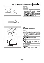
Page 57: ...the rear axle does not turn when loosening the nut Use the axle nut wrench 46 mm 3 4 Elevate the rear wheels by placing the suit able stand under the frame 5 Remove rear wheels wheel hubs nut Axle nut wrench 46 mm P N 90890 01498 YM 37134 1 1 2 6 Loosen rear axle hub nuts 1 1 7 Loosen locknut 1 adjusting bolt 2 NOTE Loosen the locknut and adjusting bolt on each side of the machine ...

Page 58: ...ket 2 on the axle end and tap it with a soft hammer then pull out the rear axle to the right EBS00397 INSTALLING THE REAR AXLE 1 Install nut 1 bolts 2 a Tighten the nut with rear axle nut wrench 46 mm 3 to specification while holding the rear axle b Tighten bolts 2 Axle nut wrench 46 mm P N 90890 01498 YM 37134 T R Nut 160 Nm 16 0 m kg 115 ft lb LOCTITE T R Bolt 7 Nm 0 7 m kg 5 1 ft lb LOCTITE 2 2...

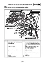
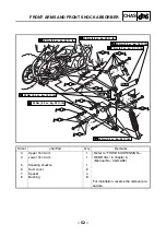
Page 59: ...S LS LS LS 3 4 1 6 6 8 7 8 6 5 6 8 7 Order Job Part Q ty Remarks Removing the front arms and front shock absorber Remove the parts in the order listed The following procedure applies to both of the front arms and front shock absorb ers Muffler exhaust pipe Refer to ENGINE ASSEMBLY AND ADJUSTMENT in chapter 4 Manual No 3GD AE5 Front wheel brake disc front brake cali per Refer to FRONT WHEEL AND WHE...

Page 60: ...ft Ib T R 48 Nm 4 8 m kg 35 ft Ib LS LS LS LS T R 7 Nm 0 7 m kg 5 1 ft Ib New New 8 8 8 6 7 8 7 6 6 6 LS LS LS LS LS 3 4 1 6 6 8 7 8 6 5 6 8 7 Order Job Part Q ty Remarks 3 Upper front arm 1 Refer to FRONT SUSPENSION REMOVAL in chapter 6 Manual No 3GD AE5 4 Lower front arm 1 5 Steering knuckle 1 6 Dust cover 8 7 Spacer 4 8 Bushing 8 For installation reverse the removal pro cedure ...

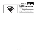
Page 61: ...RAKE REAR BRAKE ASSEMBLING THE REAR BRAKE CALIPER 1 Install parking brake arm 1 NOTE Install the parking brake arm so that the park ing brake arm to parking brake bracket dis tance a is approximately 73 mm 2 87 in a 1 ...

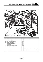
Page 62: ...er Job Part Q ty Remarks Removing the rear shock absorber and swingarm Remove the parts in the order listed Rear wheel rear axle hub Refer to REAR WHEELS AND REAR AXLE HUB Parking brake cable rear brake hose Refer to REAR SHOCK ABSORBER AND SWINGARM in chapter 6 Manual No 3GD AE5 Drive chain Refer to DRIVE CHAIN AND SPROCK ETS in chapter 6 Manual No 3GD AE5 1 Swingarm skid plate 1 2 Rear shock abs...

Page 63: ...3 ft lb LS LS LS LS LS LS LS LS LS LS 10 12 14 9 11 14 14 12 13 6 6 3 2 4 3 10 8 Order Job Part Q ty Remarks 7 Connecting rod 1 8 Oil seal bushing spacer 4 4 2 9 Drive chain guide 1 10 Pivot shaft washer nut 1 1 1 11 Swingarm 1 12 Dust cover washer oil seal 2 2 2 13 Drive chain protector 1 14 Bearing spacer 2 1 For installation reverse the removal pro cedure ...

Page 64: ...hock absorber or gas cylinder Do not subject the rear shock absorber or gas cylinder to an open flame or any other source of high heat High heat can cause an explosion due to excessive gas pressure Do not deform or damage the rear shock absorber or gas cylinder in any way If the rear shock absorber gas cylinder or both are damaged damping performance will suffer DISPOSING OF THE REAR SHOCK ABSORBE...

Page 65: ...ndicator light 4 Reverse indicator light 5 Ignition coil 6 Drive select lever switch 7 Battery 8 C D I unit 9 Starting circuit cut off relay 0 Fuse A Starter relay B Reverse switch C Neutral switch D Rear brake light switch E Wire harness 3 4 2 5 6 8 7 9 0 A C B D 1 E ELECTRICAL COMPONENTS ...

Page 66: ......

Page 67: ......

Page 68: ...YAMAHA MOTOR CO LTD 2500 SHINGAI IWATA SHIZUOKA JAPAN ...

Page 69: ...Br L B R B R W R B Br BLACK BLACK B Y L 1 A C magneto 2 Rectifier regulator 3 Main switch 4 Battery 5 Fuse 6 Starter relay 7 Starter motor 8 Clutch switch 9 C D I unit 0 Ignition coil A Spark plug B Starting circuit cut off relay C Drive select lever switch D Neutral switch E Indicator light assembly F Neutral indicator light G Reverse indicator light H Reverse switch I Rear brake light switch J F...

Reviews:

Related manuals for Raptor YFM350S