background image

57 

be cleared from memory once the scan has been stopped and the page is 
redirected away from.  To save the scan result, take a screenshot of the page 
before navigating away, and store it using your preferred image editing 
application. 

If you navigate away from the page while a scan is running, the scan will 
continue in the background as other parts of the Web UI are used or even if the 
web interface is closed, as long as the antenna or base is not rebooted.  
However, only Average and Peak data will be calculated, no graphical data will 
be provided for such times. 

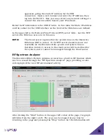
The red part of the scan represents the percentage of the RF that is currently in 
use, the blue is RF space that shows noise, but could be used by the Executive 
Elite system, and green represents available RF space.  As each snapshot of the 
RF environment is added to the graph, the average is calculated and displayed 
in a column beside it, and the peak activity so far is displayed next to that.   

The table to the right of the graph shows a guideline for additional 
microphones the RF Environment might support at either average or peak 
activity, calculated for each of the Executive Elite’s System Audio modes.   The 
number of actual microphones that can be added might be reduced in 
environments with other heavy DECT traffic or when PHS is detected (Japan 
only). 

While the graph is set up to display information over a 10 minute period, the 
longer the scan is allowed to run, the better estimate it can provide on average 
and peak activity for the local RF environment.  Running the RF scan does not 
impact microphone functionality.  The scan can run while all microphones are 
being used with no impact on audio performance. 

RF Power 

Summary of Contents for Revolabs Executive Elite 03-ELITEEXEC8-AU

Page 1: ...Executive Elite Wireless Microphone System Installation and Operation Guide Models 01 ELITEEXEC8 01 ELITEEXEC4 03 ELITEEXEC8 EU 03 ELITEEXEC4 EU 03 ELITEEXEC8 AU 03 ELITEEXEC4 AU 03 ELITEEXEC8 JP 03 ELITEEXEC4 JP ...

Page 2: ...t may be reproduced in any form or by any means without express written permission from Yamaha UC Inc Product specifications are subject to change without notice Revolabs Executive Elite Installation and Operation Guide 01 EXECELITEGUIDE EN September 2018 Rev 1 1 11 ...

Page 3: ... Components 14 Installation 17 Base DSP Unit 17 Remote Antenna Receiver 19 Connect Remote Antenna Receiver to Base DSP Unit 22 System set up 23 Revolabs Executive Elite Audio Connections 23 Synchronizing Executive Elite units 24 Front panel user interface 26 Home Screens 27 Front Panel Menu Tree 31 Main Menu 31 Front Panel Warning messages 37 Local Web UI 38 Connecting to the local web UI 38 First...

Page 4: ...84 Elite Wireless XLR Adapter 86 The Elite Wireless TA4 mini XLR Adapter for lapel and ear set microphones 88 Batteries 90 Pairing Wireless Microphones to Remote Antenna and Base DSP Station 90 LED patterns 92 Mute Groups 93 Warranty 96 Open Source Software 97 Troubleshooting 99 Accessing the Web UI through the Front Panel USB 99 Antenna Symbol Blinking 99 Batteries incorrectly detected as non rec...

Page 5: ...stem This system utilizes state of the art technology providing high bandwidth audio and enabling clear reliable untethered audio capture for your applications Please read this documentation carefully and follow the instructions before installing and using your Executive Elite Wireless Microphone System ...

Page 6: ...he limits for a Class B digital device pursuant to Part 15 of the FCC rules These limits are designed to provide reasonable protection against harmful interference in a residential installation This equipment generates uses and can radiate radio frequency energy and if not installed and used in accordance with the instructions may cause harmful interference to radio communications However there is...

Page 7: ...5A 01EXECMIC Revolabs Executive Tabletop Microphone IC 6455A 01EXECMICWR Revolabs Executive Wearable Microphone RF Exposure This equipment complies with FCC radiation exposure limits set forth for an uncontrolled environment The antenna s used for this equipment must be installed to provide a separation distance of at least eight inches 20 cm from all persons This equipment must not be operated in...

Page 8: ...the United States of America and Canada The Governments of the United States of America and Canada may restrict the exportation or re exportation of this product to certain destinations For further information contact the U S Department of Commerce or the Canadian Department of Foreign Affairs and International Trade The use of wireless devices and their accessories may be prohibited or restricted...

Page 9: ...EU Executive Elite System 4 Channel w o microphones 03 ELITEEXEC8 EU Executive Elite System 8 Channel w o microphones 03 ELITEMIC OM EU Elite Microphone Omni directional Tabletop 03 ELITEMIC DR EU Elite Microphone Uni directional Tabletop 03 ELITEMIC GN6 EU Elite Microphone 6 Inch Gooseneck Tabletop 03 ELITEMIC GN12 EU Elite Microphone 12 Inch Gooseneck Tabletop 03 ELITEMIC WR EU Elite Microphone ...

Page 10: ...cates that this product must not be disposed of with your other household waste Instead it is your responsibility to dispose of your waste equipment by handing it over to a designated collection point for the recycling of waste electrical and electronic equipment The separate collection and recycling of your waste equipment at the time of disposal will help conserve natural resources and ensure th...

Page 11: ...f the Executive Elite system Do not use any other accessories than Revolabs originals intended for use with this product Use of non original accessories may result in loss of performance damage to the product fire electric shock or injury The warranty does not cover product failures which have been caused by use of non original accessories Only use the power adapters provided to connect the compon...

Page 12: ...ology for audio and data applications using time division multiple access TDMA technology Directional Microphone A microphone that receives audio primarily from one direction Executive Elite Base DSP Unit The main processing unit of the Executive Elite system The Base DSP unit transforms the encrypted audio signal from the microphones into unencrypted analog or digital audio and applies audio cont...

Page 13: ...is connected to the Executive Elite Base DSP unit using a point to point Cat 5e or Cat 6 connection User Interface UI An interactive display allowing product users to control the Executive Elite system The Executive Elite offers several User Interfaces including a Web UI a Front Panel UI and the Cloud Management UI ...

Page 14: ...igital audio over AVB It supports the management interfaces front panel local web UI room control system UI as well as communication with the remote cloud based UI The Remote Antenna receiver contains all components required to receive and send audio signals from and to the microphones It includes the required diversity antennas The remote antenna also provides the scan of the RF frequency to dete...

Page 15: ...duction by providing Consistent audio input from all participants Minimize room noise Mute control Wireless encryption Automatic channel selection Full duplex audio Revolabs wireless microphones and transceivers receive signals audio commands from the remote antenna receiver while sending audio back to the antenna and the Base DSP unit There are several different microphone and microphone adapter ...

Page 16: ... might have purchased additional components like the ceiling mount kit for the remote antenna receiver or the cross over adapter to install wireless tabletop microphones permanently or semi permanently on your tables ...

Page 17: ...el LCD displaying system information 4 Navigation buttons controlling content of front panel LCD display 5 On Off switch Rear View 6 Power In Receptacle 100 240 VAC 50 60 Hz 7 Remote Antenna Connector PoE enabled 8 AVB network connector 9 LAN network connector 10 Serial port for room control interface 11 USB connector future use 12 Euroblock connector grey Executive HD compatible synchronization b...

Page 18: ...18 The Revolabs Executive Elite Base DSP Unit is designed to be installed into a standard 19 AV rack using the attached rack ears Screws are not provided ...

Page 19: ...re located Each Remote Antenna Receiver supports one Base DSP Unit If more than one Base DSP Unit is installed for a room e g more than eight microphones are required several Remote Antenna Receivers will be installed in this room It is best to install the receivers on the same wall facing into the room spaced at least 12 inches 30 cm The Remote Antenna Receiver contains several antennas to provid...

Page 20: ... network wire is connected to the Remote Antenna Receiver and routed correctly the Remote Antenna enclosure is attached to the back plate by slipping it from the top onto the two hooks and then pressing the bottom back against the wall plate until the snap clicks in To separate the Remote Antenna Receiver housing from the wall plate insert a screwdriver from the bottom into the slit and press agai...

Page 21: ...r Polar pattern of Antenna side view Antenna placement Best results are achieved when the antenna faces into the area where the microphones are used Optimal placements for the Antenna are either below the ceiling in the middle of the room facing down or high on a wall facing into the room The antenna should not be placed flat e g on a table or in a rack similar to the height the microphones are ty...

Page 22: ...s need to be installed on either end of the cable to minimize electro magnetic interference One ferrite bead should be attached of an inch 7 10 millimeters from the end of the cable that will connect to the Base DSP unit The second ferrite bead needs to be attached 5 inches 13 centimeters from the end of the cable that will attach to the antenna NOTE The Antenna Receiver provides room for the ferr...

Page 23: ...ack to the microphones Analog Audio The back panel of the Executive Elite DSP eight channel base unit provides eight 3 5mm Euroblock inputs and eight 3 5mm Euroblock outputs the four channel unit provides four input and four output connectors providing access to each channel s audio signal The Euroblock connectors included in the package are designed for easy wiring The three terminals from left t...

Page 24: ...he density of microphones that can be supported in one area Non synchronized systems in the same space block a higher number of radio frequency channels than the number of microphones they support causing RF loss and audio drop outs It is therefore important to synchronize all Executive Elite systems that are in proximity with each other to limit the number of potential audio issues There is no di...

Page 25: ... is handled differently in Executive Elite When installed together with Executive HD systems the bus will therefore only provide synchronization data not mute data between Executive Elite and Executive HD systems However mute groups managed between Executive HD systems can still be managed using the bus When selecting the synchronization bus the interface will prompt the user with a choice of Inte...

Page 26: ...hrough an AVB capable switch Select one Executive Elite system in your network as the master clock Leave the clock source of that system in Local mode All other systems that will synchronize to this master clock need their clock source to be set to AVB Then create AVB streams between the Media Clock output Talker of the Executive Elite system that is designated as your clock master and the Media C...

Page 27: ...anaging some system settings without additional equipment Its home screens provide information on audio levels radio signal strength and access to gain settings for the analog audio output The menu structure displays system information and allows changes to some system and audio settings The front panel can also be used to pair and un pair microphones It does not replace the local web UI interface...

Page 28: ...e main menu When changing the gain or entering any menu in the front control panel that allows the user to changing values a password prompt will appear before the user is allowed to proceed To enter the password use the right and left arrow keys to select a digit and the up button to change the number of that digit 0 9 Hitting Enter will submit the password and down brings the cursor to the cance...

Page 29: ...stem system is detected in the vicinity of the Executibve Elite Antenna If such a system is detected several of the DECT carrier frequencies are reserved for PHS and cannot be used for Executive Elite microphones The maximum density of microphones is therefore reduced in these environments Separated from the external systems box by a vertical line is the channel information section of the Front Pa...

Page 30: ...aid over the battery charge icon1 A microphone using a permanent cross over adapter will be shown with a power connector battery symbol A permanent cross over adapter is one where the microphone does not use batteries A battery symbol with a indicates a non rechargeable battery or wrong battery type Such a battery will not charge when placed in the charger tray The type of a battery is only determ...

Page 31: ...radio button it will select that value If it is a value entry it enables the Up and Down buttons to change the value Pressing enter again in that case will store the value and leave the data entry mode Main Menu In the main menu the first five options are sub menus that are described below The fifth entry Screen Contrast controls the contrast of the front panel when selected and the sixth entry Re...

Page 32: ...phone Information submenu paired microphones are listed Selecting any of these microphones will present the information on that specific System Info 1 Base Information 2 Antenna Information 3 Microphone Information 4 Network Information Base Information 1 FW Version 2 Product Version 3 System Name 4 Product Name Antenna Information 1 Link Status 2 MAC Address 3 FW Version Microphone Information 1 ...

Page 33: ...tion in the back of the Elite base DSP unit This includes the link status the MAC address of the interface the PTP mode and the MAC address of the AVB master System Settings The System Settings submenu allows the user to control some of the Executive Elite s system settings The Remote Management checkbox at the top of the menu enables and disables the room control CLI interface on the base DSP uni...

Page 34: ...y We recommend testing with different RF settings and using the RF Spectrum Analyzer in the local web UI to gauge the effect of the different settings Auto Scaling should be disabled except in high RF environments as it allows the system to automatically reduce RF power when it is not required The System Clock menu allows setting the synchronization mode of the Executive Elite system After selecti...

Page 35: ...ther or in proximity with legacy Revolabs systems Executive HD the Legacy Mode selection should be used for best integration Compared to the HD audio implementation in Executive Elite Legacy Mode requires more RF space per microphone It should be turned off in environments where no Executive HD systems are present The back channel audio checkbox enables or disables return audio from the base to th...

Page 36: ... an existing system are being exchanged The wizard allows channels to be skipped during the process and may therefore be used to pair less than a full set of microphones to a system as well Selecting an individual microphone will open options based on the current status of the microphone on that channel Any channel with a microphone paired to it can unpair that microphone A microphone can also be ...

Page 37: ...libration might be advantageous it will suggest a tuning of the internal clocks Tuning will take several minutes and audio flow will be impacted during the tuning We recommend tuning only systems that have run for at least several minutes to ensure operating temperature has been reached ...

Page 38: ...ully installed If this occurs connection to the web interface of the Executive Elite System cannot be established through the USB port This is likely due to your computer s driver update configuration If the problem continues please check if your computer has auto update disabled and or contact your administrator Once the driver is installed the front panel LCD will show an overlay with the IP add...

Page 39: ...this password is changed either through the front panel or the web UI both interfaces will require the new changed password After entering the password and clicking on the Login button the web interface will progress to the next page The checkbox on the bottom of the password entry form will prevent the Web UI from timing out during a period of inactivity The Web UI will still log out 60 seconds a...

Page 40: ... It is mandatory to provide a name Country Region is required to define wireless settings in the system You need to select the country or region in which the system is being used NOTE Selecting a different region than the region you are using the system in may void your right to use the system If you are unsure about which region to select please contact Yamaha support For Executive Elite units aq...

Page 41: ...t are not supposed to coordinate behavior with other systems do not provide a Cluster Name If you are not sure whether this system will be part of a Cluster or you currently do not know the cluster name do not provide a name at this time You can enter a Cluster Name later through the System Configurations page of the web user interface Click Next once you have provided the information on this page...

Page 42: ...e preference you may allow Java to run just this time or always If Java is not enable on your computer or you do not allow the Java applet to run or your web browser does not support Java plug ins the local web UI cannot provide all of the system information changes to settings might not be communicated to the Executive Elite base DSP and the user might be barred from some features of the web UI F...

Page 43: ...ed microphone the Monitor page provides the type of microphone the current status the battery charge percentage the current audio output level and the strength of the radio signal of the microphone as detected by the remote antenna The Mute Control area provides information on mute group settings and the current mute setting per microphone or per group This area allows changing microphone settings...

Page 44: ...D mute behavior is set per microphone Tray LED Behavior Hovering over this selection will open a sub menu allowing changes to the LED behavior of the microphone while in the charger Factory default is solid red while charging solid green for a fully charged microphone This can be changed to flashing red for a charging microphone and solid red for a charged microphone The charging LED behavior is s...

Page 45: ...or the analog audio output Input Signal The Input Signal area allows trimming the input signal for each microphone separately allowing for input levels of different microphones to be optimized individually For XLR and TA4 adapters an additional pre gain stage is offered The Revolabs microphones omni directional directional gooseneck and wearable are set to provide signals on the same level with a ...

Page 46: ...w mid 250 Hz 489 Hz 1 000 Hz Mid hi 1 000 Hz 1 739 Hz 3 000 Hz Hi 3 000 Hz 4 450 Hz 6 000 Hz Gain adjustment is up to 10dB around the center frequency within the band with drop off to 0dB adjustment at the border frequencies Analog Output When selecting Analog Output the VU meter shows the audio signal as provided to the analog ports The final gain stage provided here allows gain or trim to be app...

Page 47: ...or non clustered Executive Elite Base DSPs are on the same network or using the same synchronization bus the Mute Groups in each of these Clusters and unclustered Executive Elite Base DSPs are independent of each other and do not affect the maximum number of mute groups in each Cluster or Base DSP NOTE Mute group names should be using characters and numbers only starting with a character Group nam...

Page 48: ...tallation To manage and change a group the group needs to be the active group on the right side of your screen The group name of the active group is shown in the Group field 2 To select a different group as the active group either select it from the drop down in the Group field in the right column or click on the Edit button 3 of that group in the left column The group will now be opened on the ri...

Page 49: ... First the chairman mutes all microphones except itself Touching the mute area again all microphones in the group including the chairman are being muted The next touch on the mute area will unmute all microphones Please note that while the chairman mutes all other microphones in the group except itself the green LED on the microphone blinks in a more rapid pattern to identify this stage Even when ...

Page 50: ...ides double the bit rate for audio transfer over the wireless link per microphone Back channel audio is audio delivered to a wearable microphone or TA4 adapter If back channel audio is selected it will be of the same audio format as the microphone audio In applications where the back channel audio is not required it can be switched off allowing the RF space to be used more efficiently and increase...

Page 51: ...m Name the serial number and the base firmware version The Remote Antenna Receiver section shows the antenna s MAC Address DECT IDs for the 2 Executive Elite 4 microphone system or 4 Executive Elite 8 microphone system basebands antennas and the antenna firmware version This section also includes information on whether the antenna is currently connected or not Across the middle of the page microph...

Page 52: ... in a cluster The Cluster name allows grouping several Executive Elite systems together for larger installations Executive Elite Systems using the same cluster name in a subnet share group and microphone mute information allowing common mute behavior to be defined across several Executive Elite systems Every Executive Elite base intended to be in that cluster has to use the exact same cluster name...

Page 53: ... about this setting please contact Yamaha support In installations where several Executive Elite systems are in proximity the systems need to be synchronized to allow for best usage of the RF space and highest number of active microphones at the same time The System Clock section sets up and controls synchronization Clock Source allows a user to specify which transport is used for the synchronizat...

Page 54: ...tory tuned or has been locally tuned Clock tuning should remain set to factory tuned unless advised by technical support to retune the system or advised by the system itself that it detected that an internal clock fine calibration might be advantageous ...

Page 55: ...lds It is important that this information be filled out correctly before saving changes as otherwise the Executive Elite system will not be accessible through the IP connection NOTE If the network settings are configured incorrectly it can cause the Elite to become disconnected from the network making access to the Web UI over the LAN impossible even to fix the network configuration settings Howev...

Page 56: ...s that the system time on the Executive Elite base DSP is correct If the NTP servers listed here are not reachable for the Executive Elite system and system time is therefore incorrect access to the cloud server will be declined for the system and it cannot be managed through the cloud server RF Spectrum Analyzer The Executive Elite s Remote Antenna receiver has a built in RF Scanner which can be ...

Page 57: ...reen represents available RF space As each snapshot of the RF environment is added to the graph the average is calculated and displayed in a column beside it and the peak activity so far is displayed next to that The table to the right of the graph shows a guideline for additional microphones the RF Environment might support at either average or peak activity calculated for each of the Executive E...

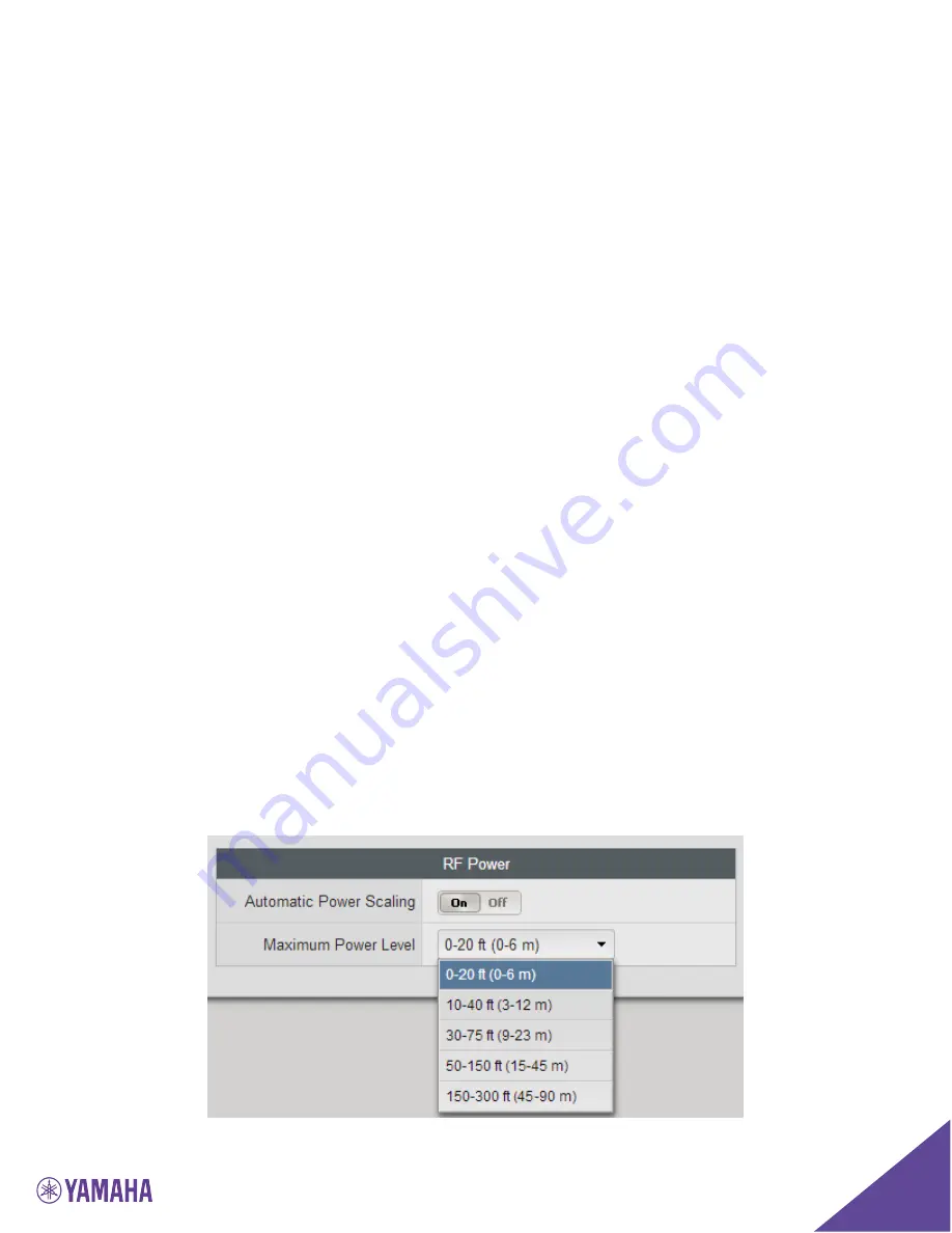
Page 58: ...ts own output This way a microphone closer to the antenna can reduce its RF impact by limiting the RF signal Automatic Power Scaling should be enabled in installations that require high transmit power settings long distances and include multiple Executive Elite Systems We recommend experimenting with several different RF settings to find the best one for your RF needs External Control Configuratio...

Page 59: ...level of the messages that will be retrieved Below that system configuration settings can be exported and imported Importing a configuration will overwrite all currently active settings in this Executive Elite System Export and Import can be used to easily duplicate settings from one Executive Elite Base DSP to another On the right hand side of the page the components of the Executive Elite can be...

Page 60: ...ill restart the initial installation dialog to collect system name region and cluster information Cloud registration information is not deleted as part of the system reset If a system was registered before the cloud registration window will not open Microphone pairing information is also not affected by restoring Factory Defaults previously paired microphones are still paired to the system If micr...

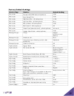
Page 61: ...individual Individual Manage Groups Unmute at Startup Off System Audio Legacy Mode Off System Audio Mic Audio SD HD SD starting with Firmware release 1 1 9 HD for firmware releases before 1 1 9 System Audio Back Channel Audio None SD HD None System Audio Back Channel Audio Source Analog AVB Analog Sys Config System Name empty Sys Config Cluster Name empty Sys Config Password 7386 Sys Config Enable...

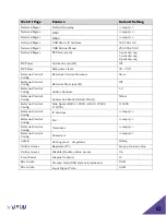
Page 62: ...62 Network Mgmt Static IP Address empty Network Mgmt Subnet Mask empty ...

Page 63: ... Control Config External Mute on off Off External Control Config Audio channels 1 2 External Control Config Connection Mode Serial Telnet Telnet External Control Config Line Speed 9600 19200 38400 57600 115200 115200 External Control Config IP Address empty External Control Config Port empty External Control Config Username empty External Control Config Password empty Admin Set Log level dropdown ...

Page 64: ...e registration request page in the Initial Setup wizard Selecting cancel on the popup navigates back to the Monitor page For a system registered to the Cloud Server revoCloud Access will lead to a Cloud Server permissions page instead of the registration page The Cloud Server permission page lists the account the system is registered to and allows enabling or disabling online access To take advant...

Page 65: ...f that release doesn t match the current firmware on the Executive Elite system the Executive Elite will offer to upgrade through the Cloud This method will not work if the Executive Elite has not been registered or Cloud Server access is disabled 2 Browse for Software File requires a software bundle to exist on a computer or server the Elite s Web UI has access to Browse to the software file sele...

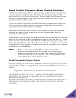
Page 66: ...eb UI When external mute is On the Executive Elite base DSP will always pass audio even when the microphones show that they are muted In this case it is the responsibility of the installer to ensure that mute is performed in an external component of the installation NOTE Both a control system and DSP cannot be connected to an Executive Elite Base Station at the same time When using a control syste...

Page 67: ...ame way the Executive HD s command interface was configured The Command Interface of the Executive Elite has been expanded significantly with additional and new functionality These commands will not work with Revolabs Executive HD systems Channel The options for the Channel portion of the serial strings are 1 8 for an Executive Elite 8 and 1 4 for an Executive Elite 4 system since each Base statio...

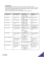
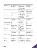
Page 68: ...atterystatus get batterystatus ch channel number Retrieve the given microphone s battery status get batterystatus ch channel number percentage chairmanmic get chairmanmic ch channel number Retrieve the given microphone s chairman state For response 0 non chairman 1 chairman val chairmanmic ch channel number 0 1 chairmanmic set chairmanmic ch channel number 0 1 Configure the given microphone s chai...

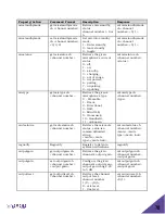
Page 69: ... Push to talk val groupmutetype group name 0 1 2 groupstandbymode get groupstandbymode groupname Retrieve group s standby mode state val groupstandbymode groupname 0 1 groupstandbymode set groupstandbymode groupname 0 1 2 Set group standby mode 1 Enter standby 0 leave standby 2 toggle val groupstandbymode default 1 legacymode get legacymode Retrieve the legacy mode setting value 0 Legacy mode off ...

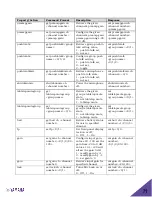
Page 70: ... s type 0 Wearable 1 Omni 2 Directional 3 XLR 4 Mini XLR 5 Gooseneck 10 Handheld 11 unknown val mictype ch channel number type mutestatus get mutestatus ch channel number Retrieve the mic mute status value is a comma delimited string mute mute type mute lock val mutestatus ch channel number mute mute type mute lock regnotify Regnotify Register to listen to system notifications regnotify outputgain...

Page 71: ... the microphone off shutdownmic ch channel number tabletopmutegroup get tabletopmutegroup group name Retrieve the given group s tabletop mute state 0 not tabletop mute 1 tabletop mute val tabletopmutegroup group name 0 1 tabletopmutegroup set tabletopmutegroup group name 0 1 Configure the given group s tabletop mute state 0 not tabletop mute 1 tabletop mute val tabletopmutegroup group name 0 1 bat...

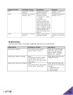
Page 72: ... state for specified channel val mute ch channel number 0 1 2 3 4 5 Notifications The Executive Elite command regnotify will turn on notifications Notifications Notification Format Description mute_group_change notify mute_group_change group name action Notify client that changes that affect a given group have occurred Actions include add add del delete ren rename mute_group_member_change notify m...

Page 73: ...na_link status Notify client antenna link status changed 0 unlinked 1 linked status_change_battery notify status_change_battery ch channel number percentage Notify client the given microphone s battery status changes status_change_mic notify status_change_mic ch channel number status Notify client the given microphone s status changed 0 off 1 on 2 standby 3 charging 4 out of range 5 not paired 6 p...

Page 74: ...74 Notifications Notification Format Description Type val type Mic type 1 Lapel Wearable 2 Omnidirrectional Tabletop 3 Directional Tabletop 4 XLR Adapter 5 Countryman Adapter ...

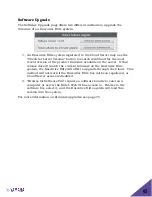
Page 75: ...are bundle accessible from the computer connected to the Executive Elite system as described on page 65 Upgrade bundles are available on Yamaha website in the support section Firmware upgrades upgrade all linked components on an Executive Elite system The Software Download pages show the progress of the Base then Antenna upgrades in that order After the upgrade is successful linked microphones wil...

Page 76: ...phones XLR adapter Revolabs Elite Wireless TA4 Adapter mini XLR adapter NOTE Before using microphones they must be paired to the Base DSP unit and Remote Antenna Each microphone is assigned a unique channel on the Base DSP unit See pairing instructions below on how to pair microphones NOTE Replace batteries only with Revolabs approved rechargeable batteries Non approved batteries or rechargeable b...

Page 77: ...attery door 4 Mute LED visual status for mute un mute and pairing 5 Battery charge status LED under the screen warns for low battery When there is approximately 2 hours of talk time remaining this LED will turn yellow When the LED turns red there is approximately 1 hour of charge remaining 6 Mute button press to mute un mute and pair microphone 7 Clip used to attach microphone to a shirt lapel blo...

Page 78: ...phones off return the microphone unit to the Charger Base or press and hold the Mute button for about 10 seconds until the LED turns solid red then release the button The microphone can also be turned off from the local web UI or the room control interface Note that in push to talk mode the microphone cannot be shut down using the mute button If the microphones are moved out of range of the Remote...

Page 79: ...icrophone Earpiece To change the volume on the Wearable microphone earpiece use the dial on the earpiece wire Turning the dial as shown in the figure will increase decrease the volume Use the attached clothing clip to secure the earpiece wire ...

Page 80: ...g tray or crossover adapted 3 Battery door latch open the battery door using this latch 4 Rechargeable batteries replace batteries only with NiMH 2000mA rechargeable batteries Non rechargeable batteries or rechargeable batteries of a different type or lower charge might impact performance of the microphone and might cause harm to the microphone users or the environment Using non approved battery t...

Page 81: ...firm by flashing green or flashing red LEDs respectively In push to talk mode touch a mute area and keep the finger there to unmute the microphone Removing the finger from a touch area will mute the microphone 4 To turn the microphone off return it to the Charger Tray or touch and hold any of the Mute areas for about 10 seconds until the LEDs turn solid red then remove the finger from the touch ar...

Page 82: ...Rechargeable batteries replace batteries only with NiMH 2000mA rechargeable batteries Non rechargeable batteries or rechargeable batteries of a different type or lower charge might impact performance of the microphone and might cause harm to the microphone users or the environment Using non approved battery types will void the warranty on the microphones When replacing the batteries ensure that th...

Page 83: ...above for an example mute or un mute the microphone by touching the mute area confirm by flashing green or flashing red LEDs respectively In push to talk mode touch the mute area and keep finger there to unmute the microphone Removing finger from a touch area will mute the microphone 4 To turn the microphone off return it to the Charger Base or touch and hold the Mute touch area for about 10 secon...

Page 84: ...attery door using this latch 4 Rechargeable batteries replace batteries only with NiMH 2000mA rechargeable batteries Non rechargeable batteries or rechargeable batteries of a different type or lower charge might impact performance of the microphone and might cause harm to the microphone users or the environment Using non approved battery types will void the warranty on the microphones When replaci...

Page 85: ...e for example mute or un mute the microphone by touching the mute area confirm by flashing green or flashing red LEDs respectively In push to talk mode touch the mute area and keep the finger there to unmute the microphone Removing the finger from the touch area will mute the microphone again 4 To turn the microphone off return it to the Charger Tray or touch and hold the Mute touch area for about...

Page 86: ... the battery door Replace batteries only with Revolabs approved rechargeable batteries 4 Battery charge status LED warns for low battery When there is approximately 2 hours of talk time remaining this LED will turn yellow When the LED turns red there is approximately 1 hour of charge remaining 5 Mute LED visual status for mute un mute and pairing 6 Mute button press to mute un mute and pair microp...

Page 87: ... the microphone again 5 To turn the XLR adapter off return the unit to the Charger Base or press and hold the Mute button for about 10 seconds until the LED turns solid red then release button The adapter can also be turned off from the local web UI or the room control interface In push to talk mode the adapter cannot be shut down using the mute button NOTE Do not place the XLR adapter into the Ch...

Page 88: ...ce batteries only with Revolabs approved rechargeable batteries 4 Battery charge status LED warns for low battery When there is approximately 2 hours of talk time remaining this LED will turn yellow When the LED turns red there is approximately 1 hour of charge remaining 5 Mute LED visual status for mute un mute and pairing 6 Mute button press to mute un mute and pair microphone 7 Clip used to att...

Page 89: ...lk mode press the mute button and keep the finger there to unmute the microphone Removing the finger from the mute button will mute the microphone again 5 To turn the mini XLR adapter off return the unit to the Charger Base or press and hold the mute button for about 10 seconds until the LED turns solid red then release the button The adapter can also be turned off from the local web UI or the roo...

Page 90: ...disassemble batteries or attempt to charge outside the system Do not dispose of batteries in fire Dispose of batteries in accordance with manufacturer s instructions and local regulations Pairing Wireless Microphones to Remote Antenna and Base DSP Station Pairing creates a link between the Elite wireless microphone and the Base DSP Unit through the Remote Antenna with a unique electronic serial nu...

Page 91: ...mute button to turn the unit off the LED will turn off Note that the microphone beeps once after about 5 seconds while holding the mute button This does not indicate that the microphone is switched off 2 Place the microphone into pairing mode by touching the Mute area or holding the mute button for several seconds until the LED turns solid red and then release the touch area or button The LED firs...

Page 92: ...ered off or battery discharged Two red flashes every 1 5 seconds Two red flashes every 1 5 seconds Microphone paired and muted One green flash every 1 5 seconds One green flash every 1 5 seconds Microphone paired and live unmuted One red flash every 1 5 seconds One red flash every 1 5 seconds Microphone paired and system muted ex tabletop mute Solid red Solid red Pairing mode or confirmation of po...

Page 93: ...e Groups With Executive Elite Revolabs introduces a very flexible way to define microphone groups The main reason for microphone groups is to define a common mute behavior between the microphones therefore the name Mute Groups Beside a common mute behavior within the group the Web User Interface also allows to monitor and manage microphones within one group The web user interfaces allows creating ...

Page 94: ...to Talk In a group that is set to Push to Talk all microphones are muted unless the mute area is touched While it is touched the microphone is in the unmuted state Each microphone controls its own mute behavior only and touching the mute area of one microphone will have no effect on other microphones in the group Because the touch area of a microphone in a Push to Talk group must be held continuou...

Page 95: ... in the group can unmute at this time Touching the mute area on the chairman microphone a third time will put the group back into the first state again The Web UI allows these three mute states to be activated individually through the Monitor page Mute lock Mute lock allows locking the mute areas on each microphone separately When mute lock is enabled the touch areas of the microphone are disabled...

Page 96: ...or equipment damaged by negligence accident or Acts of God voids this warranty The Seller shall not be liable for any consequential damage resulting from the malfunction of this product Should the user experience unsatisfactory performance from this equipment contact the Seller to obtain instructions for return or replacement as deemed necessary This warranty is not transferable by the original en...

Page 97: ...enses gpl 2 0 html GNU LGPLv2 1 http www gnu org licenses lgpl 2 1 html GNU GPLv3 http www gnu org licenses gpl html Apache http www apache org licenses LICENSE 2 0 html Oracle http www oracle com us corporate contracts license service agreement index html Postfix IBM Public http opensource org licenses IPL 1 0 MIT http opensource org licenses MIT BSD http opensource org licenses BSD 2 Clause BSD ...

Page 98: ...ls 1 0 GNU GPLv1 Udev 055 GNU GPLv2 Busybox 1 00 GNU GPLv2 Buildroot 2013 08 1 GNU GPLv2 Glibc 2 3 3 GNU LGPLv2 1 XMOS AVB 5 2 XMOS License USB Audio 2 0 XS1 L2 Software 5 3 XMOS License Opus on mic 0 9 5 BSD 2 clause Opus in base 1 0 1 BSD 3 clause Mini gmp 5 1 0 GNU LGPLv3 JamVM 1 5 4 GNU GPLv2 GNU Classpath 0 98 GNU GPLv3 Qt 4 6 3 GNU LGPLv2 1 Tecla library 1 6 2 Free Software License C CGI lib...

Page 99: ... Base DSP Unit and Antenna are not communicating During a firmware update after the base upgraded its firmware this state might persist for up to 10 minutes while antenna firmware is being updated If no update occurred recently ensure that the antenna cable is plugged into the back of the Elite Base Unit and into the Remote Antenna If the cable is connected correctly restart the Remote Antenna fro...

Page 100: ...laced into the charger and a full charge was applied Executive Elite will assume that a battery newly placed or replaced in the microphone has a 35 charge level until it can determine the real charge level Technical Support If you are experiencing technical problems or if you have questions about the operation configuration or troubleshooting of any Revolabs product please visit https uc yamaha co...

Page 101: ... 10 x 1 75 in 19 8 x 25 4 x 4 4 cm 16 oz 0 45 kg Microphone Omni Directional Tabletop 3 125 x 3 125 x 1 125 in 7 9 x 7 9 x 2 9 cm 4 7 oz 134 g Directional Tabletop 3 125 x 3 125 x 1 75 in 7 9 x 7 9 x 4 4 cm 5 0 oz 141 g 6in Gooseneck 3 125 x 3 125 x 1 75 in 7 9 x 7 9 x 4 4 cm with a 6 in gooseneck 6 8 oz 192 g 12in Gooseneck 3 125 x 3 125 x 1 75 in 7 9 x 7 9 x 4 4 cm with a 12in gooseneck 7 7 oz 2...

Page 102: ...102 Microphone Polar Patterns Elite Omni Directional Wireless Tabletop Microphone Elite Directional Wireless Tabletop Microphone ...

Page 103: ...Display 79 88 90 Mute Button 79 88 90 Pocket Clip 79 88 90 Microphones 79 Pairing 92 Polar Patterns 103 Safety Information 6 Synchronizing 23 AVB Synchronization 24 Synchronization Bus 24 Synchronization method 23 System Components Base Station 14 Microphone Charger Base 14 Wireless Boundary Microphone 82 84 XLR Microphone Wireless Adapter 90 ...

Page 104: ...om Yamaha UC EMEA 190 High Street Tonbridge Kent TN9 1BE UK 44 0 1732 366535 uc salesemea music yamaha com Yamaha UC APAC 852 8108 8820 uc salesapac music yamaha com Revolabs Executive Elite Installation and Operation Guide 01 EXECELITEGUIDE EN September 2018 Rev 1 1 11 Copyright 2018 Yamaha Unified Communications Inc ...

Reviews: