background image

English

Rear Panel

 Owner’s Manual

13

Rear Panel

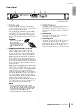
C

AC IN Connector

Connect the supplied AC power cord here. First, 
connect the power cord to the device, then insert the 
power cord plug into the AC outlet.
The supplied power cord features a special latching 
mechanism (V-LOCK) to prevent the power cord 
from being accidentally disconnected. Connect the 
power cord by inserting the power cord fully until it is 
locked.

CAUTION:

Be sure to turn the power off 
before connecting or 
disconnecting the power cord.
Press the latch button on the 
plug to disconnect the power 
cord.

D

[PRIMARY]/[SECONDARY] Connectors

The Ri8-D/Ro8-D can be connected to other 
Dante-compatible devices (such as a CL-series 
product) via these RJ45 connectors using standard 
Ethernet cables (CAT5e or better recommended).
If DIP switch 4 on the front panel is set upward (to 
DAISY CHAIN), audio signals coming into one of 
these connectors will be output from the other. Refer 
to “Daisy Chain Network” in the “About Connections” 
section (see page 14) for more information on daisy 
chain connections.
If DIP switch 4 on the front panel is set downward (to 
REDUNDANT), the [PRIMARY] connector will be 
used for primary connection, and the [SECONDARY] 
connector will be used for secondary (backup) 
connection. If the unit is unable to transmit signals 
through the [PRIMARY] connector for some reason 
(e.g., due to damage or accidental removal of the 
cable, or a failed network switch), the [SECONDARY] 
connector will automatically take over the 
connection. Refer to “About Redundant Networks” in 
the “About Connections” section (see page 14) for 
more information on redundant networks.

NOTE

Use STP (shielded twisted pair) cable to prevent 
electromagnetic interference. Make sure that the metal 
parts of the plugs are electrically connected to the STP 
cable shield by conductive tape or comparable means.

Connect only Dante-compatible devices or 
GbE-compatible devices (including a computer).

E

[LINK/ACT] Indicators

These indicators show the communication status of 
the [PRIMARY] and [SECONDARY] connectors.
They flash fast if the Ethernet cables are connected 
properly. 

F

[1G] Indicators

These indicators light when the Dante network is 
functioning as Giga-bit Ethernet.

G

Grounding screw

Grounding of chassis shall be sufficiently connected 
via a power supply cord as long as AC socket is 
grounded since the attached power supply cord is a 
triplex cable.In addition, connecting this screw to 
ground may prevent hum noise or interference noise.

C

E

F

D

G

* Illustration shows Ri8-D.

Summary of Contents for Ro8-D

Page 1: ...spañol Português Italiano Русский Ё 日本語 Owner s Manual Bedienungsanleitung Mode d emploi Manual de instrucciones Manual do Proprietário Manuale di istruzioni Руководство пользователя Փ 䇈ᯢк Փ 䇈ᯢк 取扱説明書 JA ZH RU IT PT ES FR DE EN ...

Page 2: ...nd a third grounding prong The wide blade or the third prong are provided for your safety If the provided plug does not fit into your outlet consult an electrician for replacement of the obsolete outlet 10 Protect the power cord from being walked on or pinched particularly at plugs convenience receptacles and the point where they exit from the apparatus 11 Only use attachments accessories specifie...

Page 3: ...connecting this product to accessories and or another product use only high quality shielded cables Cable s supplied with this product MUST be used Follow all installation instructions Failure to follow instructions could void your FCC authorization to use this product in the USA 3 NOTE This product has been tested and found to comply with the requirements listed in FCC Regulations Part 15 for Cla...

Page 4: ...Owner s Manual 4 ...

Page 5: ...Control 16 Control from an Ri8 D native Device 16 Control from a Device That Does Not Feature Ri8 D Native Support 16 Head Amplifier Parameters That Can be Monitored and Controlled 16 Troubleshooting 17 Troubleshooting 17 Messages 18 Specifications 135 General Specifications 135 Analog Input Characteristics Ri8 D only 136 Analog Output Characteristics Ro8 D only 136 Digital I O Characteristics 136...

Page 6: ...e basic precautions listed below to avoid the possibility of physical injury to you or others or damage to the device or other property These precautions include but are not limited to the following When removing the electric plug from the device or an outlet always hold the plug itself and not the cord Pulling by the cord can damage it Remove the electric plug from the outlet when the device is n...

Page 7: ...ional purposes only and may appear somewhat different from those on your device The company names and product names in this manual are the trademarks or registered trademarks of their respective companies Specifications and exterior appearance may be subject to change without prior notice as a result of improvements weee_eu Yamaha cannot be held responsible for damage caused by improper use or mod...

Page 8: ... Ethernet cable to a computer that has a Dante Virtual Soundcard installed enables you to directly input or output audio signals without using an audio interface device the Ri8 D is for input and the Ro8 D is for output only Firmware Updates This product enables you to update the unit firmware to improve operations add functions and correct possible malfunctions The following two types of firmware...

Page 9: ...nse to you Dante uses high accuracy network synchronization standards to achieve sample accurate playback with extremely low latency and jitter Four types of latency are available on the Ri8 D Ro8 D 0 25 msec 0 5 msec 1 0 msec and 5 0 msec Dante supports redundant connections via primary and secondary networks to defend against unforeseen difficulties Connecting a computer to Dante network over Et...

Page 10: ...nnect a device to an INPUT while phantom power is applied Doing so can damage the connected device and or the unit itself To prevent possible damage to speakers make sure that power amplifiers and or powered speakers are turned OFF when switching phantom power ON or OFF We also recommend setting all digital mixing console output controls to minimum when turning phantom power ON or OFF Sudden high ...

Page 11: ...onnections If the unit is unable to transmit signals through the PRIMARY connector for some reason e g due to damage or accidental removal of the cable or a failed network switch the SECONDARY connector will automatically take over communications and functions on the redundant network Refer to About Redundant Networks in the About Connections section see page 14 for more information on redundant n...

Page 12: ...al input phantom power settings are ON However the 48V indicators will light on channels for which phantom power is turned ON even if the 48V MASTER switch is OFF A Power Indicator Lights when AC power to the unit is ON B Power Switch Turns power to the unit ON or OFF CAUTIONS Rapidly turning the unit on and off in succession can cause it to malfunction After turning the unit off wait for about 6 ...

Page 13: ...usedforprimary connection and the SECONDARY connector will be used for secondary backup connection If the unit is unable to transmit signals through the PRIMARY connector for some reason e g due to damage or accidental removal of the cable or a failed network switch the SECONDARY connector will automatically take over the connection Refer to About Redundant Networks in the About Connections sectio...

Page 14: ...rol and monitor the network such as Qos the ability to assign priority to data flows e g clock synchronization or audio transmission on certain data circuits With this topology it is common to configure a redundant network so that an unexpected network problem will not affect any audio or otherwise stable communications About Redundant Networks A redundant network consists of two circuits a primar...

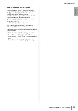
Page 15: ...ownload the latest Dante Controller from the following website Please note that Dante Controller Version 3 2 1 or later supports Ri8 D Ro8 D http www yamahaproaudio com To run Dante Controller a computer must feature a GbE compatible Ethernet connector Refer to the Dante Controller owner s manual for details on Dante Controller In Dante Controller make the following basic settings Network View Rou...

Page 16: ... LS9 DM1000 DM2000 PM5D DSP5D DME64N 24N Setting the DIP Switches While the power to the unit is off flip DIP switch 5 down and DIP switch 6 up Setting the UNIT ID Setting the Ri8 D in AD8HR will set UNIT ID as virtual ID as AD8HR Device ID If you combine Rio3224 D or Rio1608 D or add an AD8HR or SB168 ES in the network make sure that the IDs are all unique Set the Ri8 D correctly so that you can ...

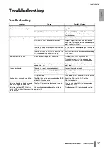
Page 17: ...e Ri8 D The input level is too low A condenser microphone is connected Turn the 48V MASTER switch ON Turn phantom power for the corresponding channel s ON from the Ri8 D native device The internal head amplifier gain is not set to an appropriate level Set the internal head amplifier gain to an appro priate level No sound is heard The cables are not connected properly Connect the cables properly Th...

Page 18: ...ler UNIT ID is not unique Set a unique UNIT ID number for the Dante network The DIP switches are not set correctly Check the DIP switch settings and set them correctly Flash x2 Flash x3 Flash x3 Light Light Flash SYNC Indicators Description Possible Solution The word clock is not set correctly Set the clock mas ter and sampling frequency correctly on the Ri8 D Ro8 D native device or in Dante Contr...

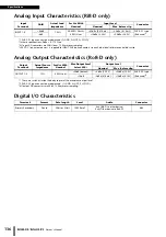
Page 19: ...octave filter 80kHz Less than 0 05 20Hz 20kHz 4dBu into 600Ω Fs 44 1kHz 48kHz Less than 0 05 20Hz 40kHz 4dBu into 600Ω Fs 88 2kHz 96kHz INPUT to OUTPUT 1 Input Gain Min Hum Noise 3 3 Hum Noise are measured with A Weight filter 128dBu typ Equivalent Input Noise Input Gain Max 88dBu Residual output noise ST master off Dynamic Range 112dB typ DA Converter 108dB typ INPUT to OUTPUT 1 Input Gain Min Cr...

Page 20: ...tput DA converters are 24bit 128times oversampling Digital I O Characteristics Input Terminals GAIN Actual Load Impedance For Use With Nominal Input Level Connector Nominal Max before clip INPUT 1 8 66dB 7 5kΩ 50 600Ω Mics 600Ω Lines 62dBu 0 616mV 42dBu 6 16mV XLR 3 31 type Balanced 1 6dB 10dBu 2 45V 30dBu 24 5V Output Terminals Actual Source Impedance For Use With Nominal Max Output Level Select ...

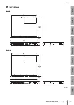
Page 21: ...English Deutsch Français Español Português Italiano Русский Ё 日本語 Dimensions Owner s Manual 137 Dimensions Ri8 D Ro8 D Unit mm 480 44 430 351 354 2 362 7 8 5 8 480 430 351 354 2 359 2 3 4 3 44 ...

Page 22: ......

Page 23: ...usic Europe GmbH Branch Italy Viale Italia 88 20020 Lainate Milano Italy Tel 02 935 771 SPAIN PORTUGAL Yamaha Music Europe GmbH Ibérica Sucursal en España Ctra de la Coruna km 17 200 28230 Las Rozas Madrid Spain Tel 34 902 39 8888 GREECE Philippos Nakas S A The Music House 147 Skiathou Street 112 55 Athens Greece Tel 01 228 2160 SWEDEN FINLAND ICELAND Yamaha Music Europe GmbH Germany filial Scandi...

Page 24: ...211IPHD A0 2012 Yamaha Corporation C S G Pro Audio Division Printed in China ZE93690 Yamaha Manual Library http www yamaha co jp manual Yamaha Pro Audio Global Web Site http www yamahaproaudio com ...

Reviews: