67
FI
FUEL INJECTION SYSTEM
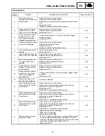
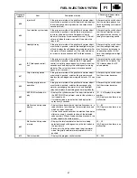
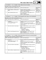
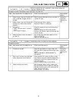
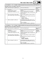
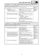
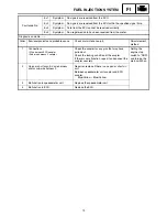
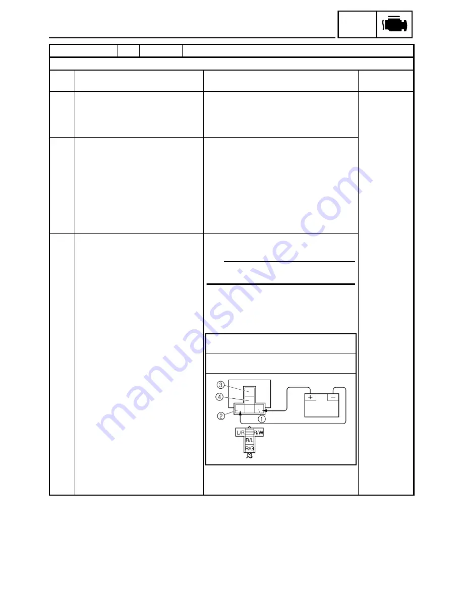
Fault code No.
43
Symptom
Power supply to the fuel injectors and fuel pump is not normal.
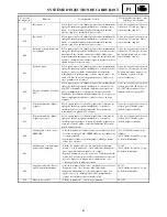
Diagnostic code No. d:09 (fuel system voltage)
Order
Item/components and probable cause
Check or maintenance job
Reinstatement
method
1
Connections
• Fuel injection system relay coupler
• Wire harness ECU coupler
Check the couplers for any pins that may have
pulled out.
Check the locking condition of the couplers.
If there is a malfunction, repair it and connect the
coupler securely.
Starting the
engine and
operating it at
idle.
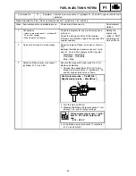
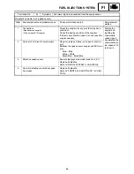
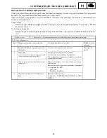
2
Open or short circuit in wire harness.
Repair or replace if there is an open or short cir-
cuit.
Between the fuel injection system relay coupler
and ECU coupler.
Blue/Red – Blue/Red
Between the fuel injection system relay coupler
and engine stop switch coupler.
Red/White – Red/White
Between the engine stop switch coupler and main
switch coupler.
Brown – Brown
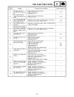
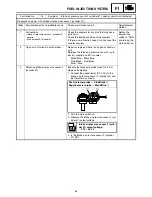
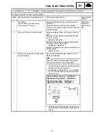
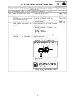
3
Malfunction or open circuit in fuel injec-
tion system relay.
Execute the diagnostic mode (code No. d:09).
Replace if defective.
TIP
When the leads are disconnected, the voltage
check by the code No. d:09 is impossible.
1. Disconnect the fuel injection system relay from
the wire harness and remove it.
2. Connect the pocket tester (
Ω
×
1) and battery
(12 V) to the fuel injection system relay termi-
nals as shown.
3. Does the fuel injection system relay have con-
tinuity between the red/green and red/blue ter-
minals?
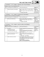
Positive battery terminal
→
Red/White
1
Negative battery terminal
→
Blue/Red
2
Positive tester probe
→
Red/Green
3
Negative tester probe
→
Red/Blue
4
Summary of Contents for RST90GTY
Page 12: ......
Page 15: ...CABLE ROUTING 102 ...
Page 19: ...ALLMÄN VÄGLEDNING FÖR ÅTDRAGNINGSMOMENT 101 DEFINITION AV ENHETER 101 KABELDRAGNING 102 ...
Page 127: ...FI ...
Page 183: ...FI ...
Page 271: ...SPEC ...
Page 272: ...102 SPEC CABLE ROUTING 8 9 0 A B C E F G C C D 1 2 3 4 5 5 6 7 A B A B ...
Page 294: ......
Page 295: ......

