background image

46

SET MENU

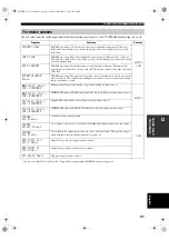
Use to manually adjust any speaker setting or compensate 
for video signal processing delays when using LCD 
monitors or projectors. Most of the SOUND MENU 
parameters are set automatically when you perform 
“BASIC SETUP” (see page 22).

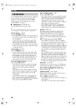
Speaker set

 A)SPEAKER SET

Use to manually adjust any speaker setting.

y

If you are not satisfied with the bass sounds from your speakers, 
you can change these settings according to your preference.

Center speaker

  CENTER

Choices: LRG, 

SML

, NONE

• Select LRG if you have a large center speaker. The unit 

directs the entire range of the center channel signal to 
the center speaker.

• Select SML if you have a small center speaker. The 

unit directs the low-frequency signals of the center 
channel to the speakers selected with “BASS OUT”.

• Select NONE if you do not have a center speaker. The 

unit directs all of the center channel signal to the front 
left and right speakers.

Front speakers

  FRONT

Choices: 

LARGE

, SMALL

• Select LARGE if you have large front speakers. The 

unit directs the entire range of the front left and right 
channel signals to the front left and right speakers.

• Select SMALL if you have small front speakers. The 

unit directs the low-frequency signals of the front 
channel to the speakers selected with “BASS OUT”.

Surround left/right speakers

  SURR LR

Choices: LRG, 

SML

, NONE

• Select LRG if you have large surround left and right 

speakers. The entire range of the surround channel 
signal is directed to the surround left and right 
speakers.

• Select SML if you have small surround left and right 

speakers. The low-frequency signals of the surround 
channel are directed to the speakers selected with 
“BASS OUT”.

• Select NONE if you do not have surround speakers. 

This will set the unit to the Virtual CINEMA DSP 
mode (see page 31) and automatically set the surround 
back speaker setting (SURR B) to NONE.

Surround back speaker

  SURR B

Choices: LRG, 

SML

, NONE

• Select LRG if you have a large surround back speaker.
• Select SML if you have a small surround back speaker. 

The low-frequency signals of the surround back 
channel are directed to the speakers selected with 
“BASS OUT”, and the rest of the frequency signals are 
directed to the surround back speaker.

• Select NONE if you do not have a surround back 

speaker. The unit directs all of the surround back 
channel signal to the surround left and right speakers.

Bass out

  BASS OUT

Low-frequency (bass) signals can be directed to the 
subwoofer and/or the front left and right speakers 
according to the characteristics of your system. This 
setting also determines the routing of the LFE (low-
frequency effect) signals found in Dolby Digital or DTS 
sources.
Choices: SWFR (subwoofer), FRONT, 

BOTH

• Select SWFR if you connect a subwoofer. LFE and 

low-frequency signals from other channels are directed 
to the subwoofer according to the speaker settings.

• Select FRONT if you do not use a subwoofer. LFE and 

low-frequency signals from other channels are directed 
to the front speakers according to the speaker settings 
(even if you have previously set the front speakers to 
SMALL).

• Select BOTH if you connect a subwoofer and you want 

to output low-frequency signals from front channels to 
both the front speakers and subwoofer. LFE and low-
frequency signals from other channels are also directed 
to the subwoofer according to the speaker settings. Use 
this function to reinforce low-frequency signals using 
the subwoofer when playing back sources such as CDs.

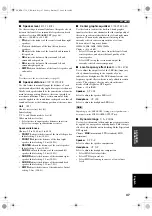
Cross over

  CrossOver

Use this feature to select a cross-over (cut-off) frequency 
for all low-frequency signals. All frequencies below the 
selected frequency will be sent to the subwoofer.
Choices: 40Hz, 60Hz, 

80Hz

, 90Hz, 100Hz, 110Hz,


120Hz, 160Hz,


200Hz

Subwoofer phase

  SWFR PHASE

If bass sounds are lacking or unclear, use this feature to 
switch the phase of your subwoofer.
Choices: 

NRM

 (normal), REV (reverse)

• Select NRM if you do not want to reverse the phase of 

your subwoofer.

• Select REV to reverse the phase of your subwoofer.

1 SOUND MENU

00_HTR-5750_U_EN.book  Page 46  Tuesday, February 17, 2004  10:29 AM

Summary of Contents for RX-V450

Page 1: ...HTR 5750 HTR 5740 AV Receiver OWNER S MANUAL U 00_HTR 5750_U_EN book Page 1 Tuesday February 17 2004 10 29 AM ...

Page 2: ...the type of power supply to your home consult your product dealer or local power company For products intended to operate from battery power or other sources refer to the operating instructions 12 Grounding or Polarization This product may be equipped with a polarized alternating current line plug a plug having one blade wider than the other This plug will fit into the power outlet only one way Th...

Page 3: ...at provides guidelines for proper grounding and in particular specifies that the cable ground shall be connected to the grounding system of the building as close to the point of cable entry as practical FCC INFORMATION for US customers 1 IMPORTANT NOTICE DO NOT MODIFY THIS UNIT This product when installed as indicated in the instructions contained in this manual meets FCC requirements Modification...

Page 4: ...ay cause fire damage to this unit and or personal injury YAMAHA will not be held responsible for any damage resulting from use of this unit with a voltage other than specified 13 To prevent damage by lightning disconnect the power cord from the wall outlet during an electrical storm 14 Do not attempt to modify or fix this unit Contact qualified YAMAHA service personnel when any service is needed T...

Page 5: ...g stations 34 Selecting preset stations 36 Exchanging preset stations 37 RECORDING 38 SOUND FIELD PROGRAM DESCRIPTIONS 39 For movie video sources 39 For music sources 41 ADVANCED OPERATIONS 42 Using the sleep timer 42 Manually adjusting speaker levels 43 Using the test tone 43 SET MENU 44 Using SET MENU 45 1 SOUND MENU 46 2 INPUT MENU 48 3 OPTION MENU 49 REMOTE CONTROL FEATURES 51 Control area 51 ...

Page 6: ... modes Remote control with preset manufacturer codes HTR 5750 only S Video signal input output capability Video signal conversion Composite video S Video capability for monitor out This document is the owner s manual for both HTR 5750 and HTR 5740 Model names are given where the details of functions are unique to each model Illustrations for HTR 5750 are mainly used for explanations y indicates a ...

Page 7: ...tment thoroughly before installing new batteries GETTING STARTED Supplied accessories TRANSMIT CODE SET STANDBY SYSTEM POWER CD MD CD R TUNER V AUX DVD AMP POWER POWER REC AUDIO MUTE MENU TITLE VOLUME DISC SKIP SET MENU LEVEL A B C D E FREQ RDS EON START MODE PTY SEEK TEST STRAIGHT ROCK JAZZ HALL STEREO 4 3 2 1 8 10 7 0 9 6 5 ENTER MOVIE TV THTR MUSIC ENTERTAIN EX ES NIGHT q DTS EFFECT DISPLAY RET...

Page 8: ...en the colon is not displayed Adjusts the level of the speaker channel selected using A B C D E NEXT when the unit is not in tuner mode 7 MEMORY MAN L AUTO FM Stores a station in the memory Hold down this button for more than 3 seconds to start automatic preset tuning 8 TUNING MODE AUTO MAN L MONO Switches between automatic tuning AUTO indicator on and manual tuning AUTO indicator off 9 VIDEO AUX ...

Page 9: ...channel or multi channel are output directly from their respective speakers without effect processing E CONTROL Use to adjust the bass treble balance for the front left and right speakers see page 26 F BASS TREBLE Use to adjust the bass treble balance for the front left and right speakers in conjunction with CONTROL G PROGRAM l h Use to select sound field programs see page 26 H INPUT MODE Sets the...

Page 10: ...he previous menu level when adjusting the SET MENU parameters 9 TRANSMIT indicator Flashes while the remote control is sending signals 0 STANDBY Sets this unit in the standby mode A SYSTEM POWER Turns on the power of this unit B SLEEP Sets the sleep timer C MULTI CH IN Selects MULTI CH INPUT when using an external decoder etc D AMP Selects the AMP mode You must select the AMP mode to control the m...

Page 11: ...types of conditions high humidity such as near a bath high temperature such as near a heater or stove extremely low temperatures dusty places Using the remote control VOLUME AUTO MAN L MONO VIDEO L AUDIO R MAN L AUTO FM LEVEL NEXT EDIT EFFECT MEMORY FM AM PRESET TUNING A B C D E l PROGRAM h BASS TREBLE l PRESET TUNING h TUNING MODE INPUT MODE CONTROL STRAIGHT SPEAKERS PHONES SILENT CINEMA STANDBY ...

Page 12: ...ones indicator Lights up when headphones are connected F SP A B indicators Light up according to the set of front speakers selected Both indicators light up when both sets of speakers are selected G SLEEP indicator Lights up while the sleep timer is on H HiFi DSP Lights when you select a HiFi DSP sound field program I Multi information display Shows the current sound field program name and other i...

Page 13: ...jack See page 12 for connection information 8 Antenna terminals See page 18 for connection information 9 Speaker terminals See page 12 for connection information 0 IMPEDANCE SELECTOR switch See page 20 Rear panel CENTER SUB WOOFER MONITOR OUT MULTI CH INPUT OUTPUT AUDIO AUDIO VIDEO S VIDEO DVD DTV CBL VIDEO R L R L IN PLAY OUT REC MD CD R CD OUT VCR VIDEO IN FRONT SURROUND TUNER AM ANT GND COMPONE...

Page 14: ...ound speakers are used for effect and surround sounds Place these speakers behind your listening position facing slightly inwards about 1 8 m 6 ft above the floor Surround back speaker SB The surround back speaker supplements the surround speakers and provides for more realistic front to back transitions Place this speaker directly behind the listening position and at the same height as the surrou...

Page 15: ...y from the monitor A speaker cord is actually a pair of insulated cables running side by side One cable is colored or shaped differently perhaps with a stripe groove or ridges Connect the striped grooved etc cable to the red terminals on this unit and your speaker Connect the plain cable to the black terminals 1 Remove approximately 10 mm 3 8 of insulation from the end of each speaker cable 2 Twis...

Page 16: ...these terminals SUB WOOFER jack Connect a subwoofer with built in amplifier such as the YAMAHA Active Servo Processing Subwoofer System to this jack SURROUND BACK terminals Connect a surround back speaker to these terminals OUTPUT SUB WOOFER SPEAKERS FRONT CENTER SURROUND SURROUND BACK R R L L A B 2 3 6 7 1 5 4 Subwoofer system Center speaker Front speakers A Surround back speaker Left Right Left ...

Page 17: ...ical jack be sure to put the cap back in place This cap protects the jack from dust Video jacks HTR 5750 This unit has three types of video jacks Connection depends on the availability of input jacks on your monitor The signals input through the S VIDEO jacks on this unit are automatically converted for output through the VIDEO jacks When V CONV is set to ON see page 49 signals input through the V...

Page 18: ...put VIDEO COMPONENT VIDEO Signal flow inside this unit HTR 5740 Output MONITOR OUT Input Connecting video components MONITOR OUT AUDIO VIDEO S VIDEO DVD VIDEO R L VIDEO COMPONENT VIDEO PR DVD MONITOR OUT PB Y DVD S VIDEO L R O DVD player Video monitor HTR 5750 U S A model Optical out Video out Audio out Video in 00_HTR 5750_U_EN book Page 14 Tuesday February 17 2004 10 29 AM ...

Page 19: ... the front and surround channels When you select MULTI CH INPUT as the input source this unit automatically turns off the digital sound field processor and you cannot select sound field programs This unit does not redirect signals input to the MULTI CH INPUT jacks to accommodate for missing speakers We recommend that you connect at least a 5 1 channel speaker system before using this feature When ...

Page 20: ... CBL VIDEO R L OUT VCR IN COMPONENT VIDEO PR DTV CBL PB Y DIGITAL INPUT DTV CBL CD COAXIAL OPTICAL O L R L R L R Cable TV or satellite tuner HTR 5750 U S A model DVD recorder or VCR Audio out Video out Optical out Audio out Video out Video in Audio in VIDEO L AUDIO R VIDEO AUX V L R Game console or video camera Video out Audio out L Audio out R 00_HTR 5750_U_EN book Page 16 Tuesday February 17 200...

Page 21: ...O R L IN PLAY REC MD CD R CD DIGITAL OUTPUT DIGITAL INPUT OPTICAL MD CD R CD COAXIAL OPTICAL MD CD R L R L R L R O O C CD player MD recorder or tape deck HTR 5750 U S A model Coaxial out Audio out Audio in Audio out Optical in Optical out 00_HTR 5750_U_EN book Page 17 Tuesday February 17 2004 10 29 AM ...

Page 22: ... reception quality an outdoor antenna may improve the quality Consult the nearest authorized YAMAHA dealer or service center about outdoor antennas 75 ohm 300 ohm antenna adapter U K model only 1 Open the cover of the included 75 ohm 300 ohm antenna adapter 2 Cut the external sleeve of the 75 ohm coaxial cable and prepare it for connection 3 Cut the lead wire and remove it 4 Insert the cable wire ...

Page 23: ...e outlet s supply power to any connected component whenever this unit is turned on The maximum power total power consumption of components that can be connected to the AC OUTLET S is Korea model N A Other models 100 W Memory back up The memory back up circuit prevents the stored data from being lost even if this unit is in the standby mode However if the power cord is disconnected from the AC wall...

Page 24: ...separate speaker systems A and B simultaneously when the switch is set to the right position CAUTION SET BEFORE POWER ON IMPEDANCE SELECTOR IMPEDANCE SELECTOR switch Switch position Speaker Impedance level Left Front If you use one set A or B the impedance of each speaker must be 4 Ω or higher If you use two sets A and B the impedance of each speaker must be 8 Ω or higher The impedance of each spe...

Page 25: ... FM LEVEL NEXT EDIT EFFECT MEMORY FM AM PRESET TUNING A B C D E l PROGRAM h BASS TREBLE l PRESET TUNING h TUNING MODE INPUT MODE CONTROL STRAIGHT SPEAKERS PHONES SILENT CINEMA STANDBY ON B A MULTI CH INPUT VIDEO AUX INPUT 1 TRANSMIT CODE SET STANDBY SYSTEM POWER CD MD CD R TUNER V AUX DVD AMP POWER POWER VOLUME TV MUTE TV INPUT TV VOL TV CH AV TV VCR DTV CBL MULTI CH IN SLEEP 1 U S A model STANDBY...

Page 26: ...es are defined as follows U S A and Canada models S small 16 x 13ft 200ft2 4 8 x 4 0m 20m2 M medium 20 x 16ft 300ft2 6 3 x 5 0m 30m2 L large 26 x 19ft 450ft2 7 9 x 5 8m 45m2 Other models S small 3 6 x 2 8m 10m2 M medium 4 8 x 4 0m 20m2 L large 6 3 x 5 0m 30m2 5 Press d to display the SUBWOOFER parameter 6 Press j i to select the desired setting YES If you have a subwoofer in your system NONE If yo...

Page 27: ...lect the desired setting CHECK OK YES YES To complete the setup process if the test tone levels from each speaker were satisfactory NO To proceed to the SP LEVEL speaker level adjustment menu to balance the level of each speaker 13 Press SELECT to confirm your selection If you selected NO in step 12 the front speaker level adjustment display appears in the front panel display Choices Display Speak...

Page 28: ...the surround left and surround right speakers SWFR Adjusts the balance between the front left speaker and the subwoofer 2 Press SET MENU to exit after balancing the speakers y You can also balance the speaker levels using test tone by pressing TEST on the remote control CD TUNER MD CD R DVD HiFi DSP DTV CBL V AUX VCR 96 24 q PL q EX MATRIX DISCRETE SILENT CINEMA NIGHT ZONE2 PTY HOLD AUTO PS RT CT ...

Page 29: ...RESET TUNING h TUNING MODE INPUT MODE CONTROL STRAIGHT SPEAKERS PHONES SILENT CINEMA STANDBY ON B A MULTI CH INPUT VIDEO AUX INPUT 1 7 4 3 6 TRANSMIT CODE SET STANDBY SYSTEM POWER CD MD CD R TUNER V AUX DVD AMP POWER POWER VOLUME TV VOL TV CH AV TV VCR DTV CBL MULTI CH IN SLEEP MUTE VOLUME STRAIGHT ROCK JAZZ HALL STEREO 4 3 2 1 8 10 7 0 9 6 5 ENTER MOVIE TV THTR MUSIC ENTERTAIN EX ES NIGHT q DTS E...

Page 30: ...eakers or headphones when connected Press CONTROL on the front panel repeatedly to select TREBLE or BASS then press BASS TREBLE repeatedly to increase or decrease Select TREBLE to adjust the high frequency response Select BASS to adjust the low frequency response To cancel the tone control press CONTROL repeatedly to select BYPASS y Speaker and headphone adjustments are stored independently If you...

Page 31: ...rst select the video source then press MULTI CH INPUT Front panel operation Press PROGRAM l h repeatedly to select the desired program The name of the selected program appears in the front panel display and video monitor Note Note MULTI CH INPUT MULTI CH IN Front panel Remote control or CD MD CD R TUNER V AUX DVD AMP VCR DTV CBL MULTI CH IN SLEEP Audio sources Video sources Selecting sound field p...

Page 32: ...signal it cannot automatically be played in 6 1 channels Decoders select with j i You can select from the following decoders depending on the format of the software you are playing PLIIxMusic For playing back Dolby Digital or DTS signals in 6 1 channels using the Pro Logic IIx music decoder EX ES For playing back Dolby Digital signals in 6 1 channels using the Dolby Digital Surround EX decoder DTS...

Page 33: ...ble when SURR B is set to NONE see page 46 Enjoying 2 channel software Signals input from 2 channel sources can also be played back on multiple channels Press q DTS on the remote control to select the decoder You can select from the following decoders depending on the type of software you are playing and your personal preference PRO LOGIC SUR STANDARD Standard processing for Dolby Surround sources...

Page 34: ...tening is selected the NIGHT indicator in the front panel display lights up Select NIGHT CINEMA when watching films to reduce the dynamic range of film soundtracks and make dialog easier to hear at lower volumes Select NIGHT MUSIC when listening to music sources to preserve ease of listening for all sounds Select OFF if you do not want to use this function Press j i to adjust the effect level whil...

Page 35: ...ce When headphones are connected to the PHONES jack This unit comes with a variety of input jacks Do the following to select the type of input signals you want to use 1 Rotate INPUT to select the input source 2 Press INPUT MODE to select an input mode In most cases use AUTO AUTO Automatically selects input signals in the following order 1 Digital signals 2 Analog signals DTS Selects only digital s...

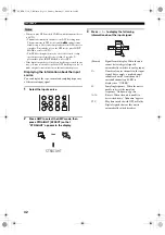
Page 36: ...of the current input signal 1 Select the input source 2 Press AMP to select the AMP mode then press STRAIGHT EFFECT so that STRAIGHT appears in the display STRAIGHT 3 Press u d to display the following information about the input signal Format Signal format display When the unit cannot detect a digital signal it automatically switches to analog input in Number of source channels in the input signa...

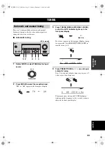
Page 37: ... TUNED indicator lights up and the frequency of the received station is shown in the front panel display TUNING Automatic and manual tuning VOLUME AUTO MAN L MONO VIDEO L AUDIO R MAN L AUTO FM LEVEL NEXT EDIT EFFECT MEMORY FM AM PRESET TUNING A B C D E l PROGRAM h BASS TREBLE l PRESET TUNING h TUNING MODE INPUT MODE CONTROL STRAIGHT SPEAKERS PHONES SILENT CINEMA STANDBY ON B A MULTI CH INPUT VIDEO...

Page 38: ...ecall any preset station easily by selecting the preset station number 1 Press FM AM to select the FM band 2 Press TUNING MODE AUTO MAN L MONO so that the AUTO indicator lights up in the front panel display If a colon appears in the front panel display tuning is not possible Press PRESET TUNING EDIT to turn the colon off AUTO MAN L MONO TUNING MODE AUTO Disappears TUNER MD CD R DVD HiFi DSP DTV CB...

Page 39: ...e MEMORY indicator flashes for about 5 seconds 3 Press A B C D E repeatedly to select a preset station group A to E while the MEMORY indicator is flashing The group letter appears Check that the colon appears in the front panel display Notes Memory back up The memory back up circuit prevents the stored data from being lost even if this unit is set in the standby mode the power cord is disconnected...

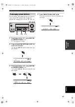
Page 40: ...EL l PRESET TUNING h CD TUNER MD CD R DVD HiFi DSP DTV CBL V AUX VCR 96 24 q PL q EX MATRIX DISCRETE SILENT CINEMA NIGHT ZONE2 PTY HOLD AUTO PS RT CT EON PTY TUNED STEREO MUTE VOLUME MEMORY SLEEP VIRTUAL PCM q PL q PL x A B SP ft mS dB dB 96 24 LFE L C R SL SB SR q DIGITAL t C 1 3 AM18630kkHz Preset number MAN L AUTO FM MEMORY CD TUNER MD CD R DVD HiFi DSP DTV CBL V AUX VCR 96 24 q PL q EX MATRIX ...

Page 41: ... NEXT EDIT EFFECT MEMORY FM AM PRESET TUNING A B C D E l PROGRAM h BASS TREBLE l PRESET TUNING h TUNING MODE INPUT MODE CONTROL STRAIGHT SPEAKERS PHONES SILENT CINEMA STANDBY ON B A MULTI CH INPUT VIDEO AUX INPUT 2 4 1 3 1 3 U S A model EDIT PRESET TUNING CD TUNER MD CD R DVD HiFi DSP DTV CBL V AUX VCR SILENT CINEMA NIGHT ZONE2 PTY HOLD AUTO PS RT CT EON PTY TUNED STEREO M MEMORY SLEEP VIRTUAL x A...

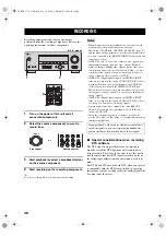
Page 42: ...NPUT jacks are not output to the analog AUDIO OUT L R jacks for recording You can only record analog signals A given input source is not output on the same REC OUT channel For example the signal input from VCR IN is not output on VCR OUT Check the copyright laws in your country to record from records CDs radio etc Recording of copyrighted material may infringe copyright laws Special considerations...

Page 43: ... the feeling you are at an actual jazz or rock concert ENTERTAINMENT Game This program adds a deep and spatial feeling to video game sounds TV THEATER Mono Movie This program is provided for reproducing monaural video sources such as old movies The program produces the optimum reverberation to create sound depth using only the presernce sound field TV THEATER Variety Sports Though the presence sou...

Page 44: ...Y EX SUR ENHANCED CINEMA DSP enhanced 6 1 channel processing Dolby Digital EX for DTS sources DTS ES Mtrx6 1 SUR STANDARD Standard 6 1 channel processing DTS ES Matrix for DTS sources DTS ES Mtrx6 1 SUR ENHANCED CINEMA DSP enhanced processing DTS ES Matrix for DTS sources DTS ES Disc6 1 SUR STANDARD Standard 6 1 channel processing DTS ES Discrete for DTS sources DTS ES Disc6 1 SUR ENHANCED CINEMA ...

Page 45: ...am recreates the acoustic environment of a lively disco in the heart of a big city The sound is dense and highly concentrated It is also characterized by high energy immediate sound q D PLIIx Music SUR STANDARD Standard Dolby Digital and Dolby Pro Logic IIx processing for music sources MULTI q D PLIIx Music SUR ENHANCED CINEMA DSP enhanced Dolby Digital and Dolby Pro Logic IIx processing for music...

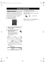
Page 46: ...EP indicator goes off y The sleep timer setting can also be canceled by pressing STANDBY on the remote control or STANDBY ON on the front panel to set this unit to the standby mode ADVANCED OPERATIONS Using the sleep timer TRANSMIT CODE SET STANDBY SYSTEM POWER CD MD CD R TUNER V AUX DVD AMP POWER POWER VOLUME TV MUTE TV INPUT TV VOL TV CH AV TV VCR DTV CBL MULTI CH IN SLEEP 2 SLEEP SLEEP 90min SL...

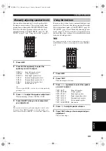
Page 47: ...ETUP page 22 SP LEVEL page 47 and Manually adjusting speaker levels page 43 Use the test tone to set speaker levels so that the volume from each speaker is identical when heard from your listening position You cannot activate the test tone if headphones are connected to the PHONES jack Remove the headphones from the PHONES jack 1 Press AMP 2 Press TEST The unit outputs a test tone 3 Press u d repe...

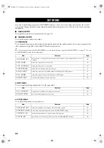
Page 48: ... Features Page A SPEAKER SET Selects the size of each speaker the speakers for low frequency signal output and the cross over frequency 46 B SP LEVEL Adjusts the output level of each speaker 47 C SP DISTANCE Adjusts the delay time of each speaker 47 D CENTER GEQ Adjusts the tonal quality of the center speaker 47 E LFE LEVEL Adjusts the output level of the LFE channel for Dolby Digital or DTS signa...

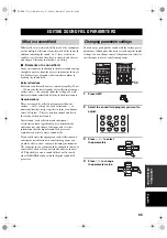
Page 49: ...the previous menu level press RETURN 7 Press u d to select the item you want to adjust then press j i to change the setting of the item Repeat this operation to select and adjust each setting To return to the previous menu level press RETURN 8 To exit press SET MENU when finished Using SET MENU Note AMP REC AUDIO MUTE MENU TITLE VOLUME SET MENU LEVEL A B C D E TEST STRAIGHT ROCK JAZZ HALL STEREO 4...

Page 50: ...ave a large surround back speaker Select SML if you have a small surround back speaker The low frequency signals of the surround back channel are directed to the speakers selected with BASS OUT and the rest of the frequency signals are directed to the surround back speaker Select NONE if you do not have a surround back speaker The unit directs all of the surround back channel signal to the surroun...

Page 51: ...ance of the surround right speaker Initial setting 3 0 m 10 0 ft SURR B adjusts the distance of the surround back speaker Initial setting 2 10 m 7 0 ft SWFR adjusts the distance of the subwoofer Initial setting 3 0 m 10 0 ft Center graphic equalizer D CENTER GEQ Use this feature to adjust the built in 5 band graphic equalizer for the center channel so that the tonal quality of the center speaker m...

Page 52: ...ectively connect more components Once the inputs have been reassigned you can select the corresponding component by using INPUT on the front panel or the input selector buttons on the remote control For COMPONENT VIDEO jacks A C V A and B C V B Choices DVD V AUX DTV CBL VCR HTR 5750 For OPTICAL OUTPUT jack 1 OUT 1 Choices MD CD R CD V AUX DTV CBL VCR DVD For OPTICAL INPUT jacks 2 IN 2 3 IN 3 and 4...

Page 53: ...ersion HTR 5750 only V CONV Use this feature to turn on off conversion of composite VIDEO signals to S Video signals This allows you to output converted video signals from the S VIDEO jacks when no S Video signals are input Choices ON OFF Select OFF not to convert any signals Select ON to convert composite signals to S Video signals Converted video signals are only output to the MONITOR OUT jacks ...

Page 54: ... set D ZONE SET Use to specify the location of speakers connected to the SPEAKERS B terminals Speaker B set SP B Use this feature to select the location of the front speakers connected to the SPEAKERS B terminals Choices FRONT ZONE B Select FRONT to turn on off SPEAKERS A and B when the speakers connected to the SPEAKERS B terminals are set in the main room Select ZONE B if the speakers connected ...

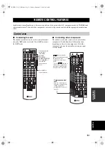
Page 55: ... 5 ENTER MOVIE TV THTR MUSIC ENTERTAIN EX ES NIGHT q DTS EFFECT DISPLAY RETURN TV MUTE TV INPUT TV VOL TV CH SELECT PRESET CH REC AUDIO MENU TITLE DISC SKIP SET MENU LEVEL A B C D E TEST STRAIGHT ROCK JAZZ HALL STEREO 4 3 2 1 8 10 7 0 9 6 5 ENTER MOVIE TV THTR MUSIC ENTERTAIN EX ES NIGHT q DTS EFFECT DISPLAY RETURN TV MUTE TV INPUT TV VOL TV CH SELECT PRESET CH REC AUDIO MENU TITLE DISC SKIP SET M...

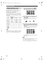
Page 56: ...ote control flashes twice 3 Press the numeric buttons to enter the four digit manufacturer s code for the component to be used Refer to LIST OF MANUFACTURER CODES at the end of this manual The TRANSMIT indicator on the remote control flashes twice If the manufacturer of your component has more than one code try each of them until you find the correct one If you wait for more than 30 seconds during...

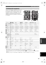
Page 57: ... MD CD recorder Tuner 1 AV POWER Power 1 Power 1 VCR power 3 Power 1 Power 1 Power 1 2 TV POWER TV power 2 TV power 2 TV power TV power 2 TV power 2 TV power 2 3 TV CH TV channel up 2 TV channel up 2 TV channel up TV channel up 2 TV channel up 2 TV channel up 2 TV CH TV channel down 2 TV channel down 2 TV channel down TV channel down 2 TV channel down 2 TV channel down 2 4 TV VOL TV volume up 2 TV...

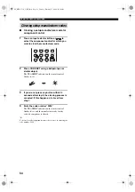
Page 58: ... press any button within 30 seconds after step 2 the clearing process is canceled If this happens start over from step 1 4 Enter the code number 0000 The TRANSMIT indicator on the remote control flashes twice and the manufacturer code for the selected component is cleared y You can clear all setup manufacturer codes at once by entering the code number 9990 Clearing setup manufacturer codes CD MD C...

Page 59: ...uces in order to create sound fields If you could create the appropriate early reflections and subsequent reverberations in your listening room you would be able to create your own listening environment The acoustics in your room could be changed to those of a concert hall a dance floor or virtually any size room at all This ability to create sound fields at will is exactly what YAMAHA has done wi...

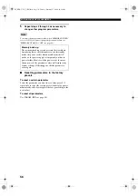
Page 60: ...ory preset the display pauses momentarily at the factory preset before proceeding to the next value To reset all parameters Use PARAM INI see page 50 Note Memory back up The memory back up circuit prevents the stored data from being lost even if this unit is set in the standby mode the power cord is disconnected from the AC outlet or the power supply is temporarily cut due to power failure However...

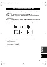
Page 61: ...from the source sound by adjusting the delay between the direct sound and the first reflection heard by the listener Description The smaller the value the closer the sound source seems to the listener The larger the value the farther it seems For a small room set to a small value For a large room set to a large value Control range 1 99 msec For 6ch Stereo Function These parameter adjusts the volum...

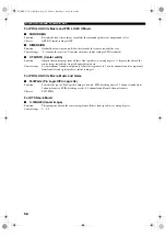
Page 62: ...usts the center image towards the front left and right speakers Control range 0 center channel sound is output only from center speaker to 7 center channel sound is output only from front left and right speakers initial setting is 3 For PRO LOGIC IIx Movie Music and Game PLII PLIIx Pro Logic II Pro Logic IIx Function Switches the type of Pro Logic decoding to be used PLII decoding creates 5 1 chan...

Page 63: ...ity Set this unit in the standby mode disconnect the power cord plug it back in after 30 seconds then use it normally No sound Incorrect input or output cable connections Connect the cables properly If the problem persists the cables may be defective 14 17 The input mode is set to DTS or ANALOG Select AUTO 31 No appropriate input source has been selected Select an appropriate input source with INP...

Page 64: ...from the center speaker The output level of the center speaker is set to minimum Raise the level of the center speaker 47 CENTER in SET MENU is set to NONE Select the appropriate setting for the center speaker 46 One of the Hi Fi DSP programs except for 6ch Stereo has been selected Try another sound field program 27 39 No sound from the surround speakers The output level of the surround speakers i...

Page 65: ...rces A source cannot be recorded by an analog component connected to the AUDIO OUT jacks The source component is not connected to this unit s analog AUDIO IN jacks Connect the source component to the analog AUDIO IN jacks 13 17 38 The sound field parameters and some other settings on this unit cannot be changed MEMORY GUARD in SET MENU is set to ON Select OFF 49 This unit does not operate properly...

Page 66: ...e manual tuning method 34 There are continuous crackling and hissing noises Noises result from lightning fluorescent lamps motors thermostats and other electrical equipment Use an outdoor antenna and a ground wire This will help somewhat but it is difficult to eliminate all noise There are buzzing and whining noises A TV set is being used nearby Move this unit away from the TV Problem Cause Remedy...

Page 67: ...e desired setting Reset To reset the unit to its factory presets Cancel To cancel without making any changes 3 Press STANDBY ON to confirm your selection If you selected Reset the unit is reset to its factory presets and switches to standby mode If you selected Cancel the unit switches to standby mode and nothing is reset RESETTING THE FACTORY PRESETS VOLUME AUTO MAN L MONO VIDEO L AUDIO R MAN L A...

Page 68: ...and a Game mode for games Dolby Surround Dolby Surround uses a 4 channel analog recording system to reproduce realistic and dynamic sound effects 2 front left and right channels stereo a center channel for dialog monaural and a surround channel for special sound effects monaural The surround channel reproduces sound within a narrow frequency range Dolby Surround is widely used with nearly all vide...

Page 69: ...is used in many critical listening rooms especially for mastering purposes LFE 0 1 channel This channel is for the reproduction of low bass signals The frequency range for this channel is 20 Hz to 120 Hz This channel is counted as 0 1 because it only enforces a low frequency range compared to the full range reproduced by the other 5 6 channels in Dolby Digital or DTS 5 1 6 1 channel systems PCM Li...

Page 70: ...tput Composite video signal With the composite video signal system the video signal is composed of three basic elements of a video picture color brightness and synchronization data A composite video jack on a video component transmits these three elements combined S Video signal With the S Video signal system the video signal normally transmitted using a pin cable is separated and transmitted as t...

Page 71: ...Ω MULTI CH INPUT 200 mV 47 kΩ Output Level Output Impedance REC OUT 200 mV 1 2 kΩ SUB WOOFER 4 V 1 2 kΩ VIDEO SECTION Video Signal Type PAL NTSC Signal to Noise Ratio 50 dB Frequency Response MONITOR OUT Composite 5 Hz to 10 MHz 3 dB Component 5 Hz to 60 MHz 3 dB S Video HTR 5750 only 5 Hz to 10 MHz 3 dB FM SECTION Tuning Range U S A and Canada models 87 5 to 107 9 MHz Other models 87 50 to 108 00...

Page 72: ... 0951 JENSEN 0311 JINXING 1531 1541 1551 1561 1571 1621 1631 1641 1651 1691 1731 JVC VICTOR 0261 0281 0641 0651 0661 0841 KAWASHO 0901 KAYPANI 1021 KENWOOD 0361 1031 1111 KLOSS 0631 0721 1131 KTV 0921 0941 1011 1051 1111 LEYCO 1001 LG GOLDSTAR 0031 0121 0351 0411 0731 0741 0861 0941 0971 1001 1031 1111 1151 LIESENK TTER 1001 LLOYTRON 0941 LOEWE 1001 LOGIK 0991 1771 LUXMAN 0351 0971 LXI 0101 0621 0...

Page 73: ...SIGMA 450 0546 OAK SIGMA 550 0536 PANASONIC TZ 120 130 0476 PANASONIC TZ 170 180 0446 PANASONIC TZ140 0466 PANASONIC TZ150 160 0456 PARAGON 0386 PHILIPS 0036 0216 0306 0316 0326 0336 0346 PIONEER 0006 0086 PIONEER BR50 0846 PIONEER BR60 70 80 81 82 0696 PIONEER BR90 0556 PULSAR 0386 RCA DIGITAL SATELLITE SYSTEM 0396 0406 REALISTIC 0136 REGENCY EASTERN0686 RUNCO 0386 SAMSUNG 0276 SCIENTIFIC ATLANTA...

Page 74: ... VIDEO CONCEPTS 0202 0432 0632 0952 WARDS 0322 0402 0472 0482 0602 0712 0842 0852 0922 0932 0992 YAMAHA 0202 0632 ZENITH 0042 0362 0512 0672 DVD PLAYER AKAI 0058 AIWA 0218 DENON 0188 HITACHI 0198 JVC VICTOR 0088 0178 KENWOOD 0148 LG GOLDSTAR 0228 MAGNAVOX 0128 MITSUBISHI 0138 ONKYO 0068 0128 PANASONIC 0028 PHILIPS 0098 0128 PIONEER 0108 0118 PROSCAN 0158 RCA 0158 SAMSUNG 0078 SHARP 0038 SONY 0018 ...

Page 75: ...415 0545 0575 1065 CD RECORDER HITACHI 0474 JVC VICTOR 0504 MARANTZ 0484 0494 PHILIPS 0444 PIONEER 0454 YAMAHA 0414 MD RECORDER KENWOOD 0384 PIONEER 0424 SHARP 0434 SONY 0394 YAMAHA 0024 0394 0404 0514 TAPE DECK AIWA 0094 0214 0224 AKAI 0184 CARVER 0094 DENON 0304 FISHER 0144 GARRARD 0194 0204 JVC VICTOR 0274 0284 0294 KENWOOD 0124 0134 0154 0234 0244 0264 MAGNAVOX 0094 MARANTZ 0094 0344 MITSUBISH...

Page 76: ...UE FRANCE S A RUE AMBROISE CROIZAT BP70 CROISSY BEAUBOURG 77312 MARNE LA VALLEE CEDEX02 FRANCE YAMAHA ELECTRONICS UK LTD YAMAHA HOUSE 200 RICKMANSWORTH ROAD WATFORD HERTS WD18 7GQ ENGLAND YAMAHA SCANDINAVIA A B J A WETTERGRENS GATA 1 BOX 30053 400 43 VÄSTRA FRÖLUNDA SWEDEN YAMAHA MUSIC AUSTRALIA PTY LTD 17 33 MARKET ST SOUTH MELBOURNE 3205 VIC AUSTRALIA 2004 All rights reserved Printed in Malaysia...

Reviews: