C 1 - 1
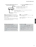
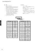
A L L : O K
C1. DIGITAL P.C.B. CHECK
This menu is used to check the communication and
bus line connection between devices on DIGITAL
P.C.B.
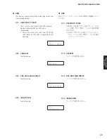
C1-1. ALL
The total detection result of sub-menus from
C1-2 to C1-8 is displayed.
C1. DIGITAL P.C.B. CHECK
DIGITAL P.C.B. 上の各デバイス間の通信とバスライン
接続をチェックします。
C1-1. ALL
サブメニュー C1-2 〜 C1-8 の総合判定結果が
表示されます。
OK: No error detected /
不良検出なし
NG: An error is detected /
不良検出あり
--: Checking
/
チェック中
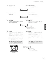
C1-2. MCPU
OSD
Microprocessor (IC21) and OSD FLASH ROM
(IC2)’s reading/writing are checked.
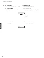
C1-3. OSD
HDMI
OSD FLASH ROM (IC2) and HDMI IC (IC1)’s
reading/writing are checked.
C1-2. MCPU OSD
マイコン(IC21)と OSD FLASH ROM(IC2)
の読み出し/書き込みをチェックします。
C1-3. OSD HDMI
OSD FLASH ROM(IC2)と HDMI IC(IC1)の
読み出し/書き込みをチェックします。
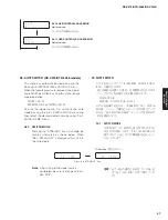
C 1 - 2
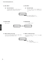
M C P U O S D : O K
C 1 - 3
O S D H D M I : O K
OK: No error detected /
不良検出なし
NG: An error is detected /
不良検出あり
OK: No error detected /
不良検出なし
NG: An error is detected /
不良検出あり
OK: No error detected /
不良検出なし
NG: An error is detected /
不良検出あり
--: Checking
/
チェック中
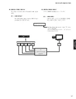
C1-4. VIDEO
I/F
Communication and bus line connection
between microprocessor (IC21) and Video
Selector (IC502) are checked.
C 1 - 4
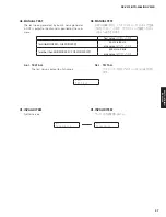
V I D E O I / F : O K
C1-4. VIDEO I/F
マイコン(IC21)と Video Selector(IC502)
間の通信とバスライン接続をチェックします。
42
RX-V475/HTR-4066/RX-V500D
RX-V475/HTR-4066/
RX-V50
0D
Summary of Contents for RX-V500D
Page 9: ...RX V500D A model RX V500D B G models 9 RX V475 HTR 4066 RX V500D RX V475 HTR 4066 RX V500D ...
Page 132: ... CONFIGURING THE SYSTEM SETTINGS RX V475 HTR 4066 RX V500D 133 ...
Page 133: ... システム設定を変更する RX V475 HTR 4066 RX V500D 134 ...
Page 146: ...147 RX V475 HTR 4066 RX V500D RX V475 HTR 4066 RX V500D MEMO ...
Page 147: ...RX V475 HTR 4066 RX V500D ...


