R 1 - 1
0
R 1 - 2
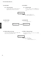
D A B : 2 1 9 8 2 . 0 2
R1. DAB (RX-V500D model)
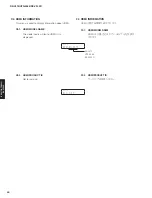
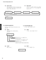
This menu is used to display the DAB module
information.
R1-1. SIGNAL
QUALITY
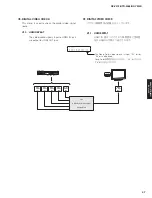
Not for service.
R1-2. DAB
MODULE
VERSION
The firmware version of DAB module is
displayed.
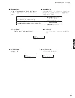
R1. DAB(RX-V500D model)
サービスでは使用しません。
R 1 - 1
I n v a l i d i t y
R 1 - 2
I n v a l i d i t y
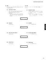
P 1 - 1
D C : 0 5 9
P1. SYSTEM MONITOR
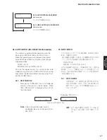
This menu is used to display the A/D conversion value
of the microprocessor which detects panel keys and
protection functions by using the sub-menu.
When “P1-7. KEY1/KEY2” sub-menu is selected, keys
become inoperable due to detection of the values
of all keys. However, it is possible to advance to the
next menu by turning the VOLUME knob.
*
Numeric values in the figure are given as reference
only.
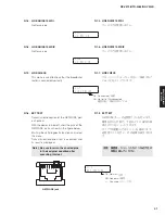
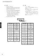
P1-1. DC
Power amplifier DC (DC voltage) output is
detected.
The voltage at 120 pin (DC_PRT) of IC21 is
displayed.
Normal value: 27 to 89
(Reference voltage: 3.3 V=255)
*
If DC becomes out of the normal value range,
the protection function works to turn off the
power.
P1. SYSTEM MONITOR
パネルキー、プロテクションなどを検出しているマ
イコンの A/D 変換値を、サブメニューで表示します。
サブメニュー “P1-7. KEY1/KEY2” にすると、全キー
の値を検出するためキー操作はできなくなりますが、
VOLUME ツマミを回すことにより、次のメニューに
進めることができます。
※ 図中の数値は参考例です。
P1-1. DC
パワーアンプ DC(直流電圧)出力の検出
IC21 の 120 ピン(DC̲PRT)の電圧が表示され
ます。
正常値:
27 〜 89
(基準電圧:3.3 V=255)
※ DC が正常値を外れるとプロテクションが
働き、電源が切れます。
49
RX-V475/HTR-4066/RX-V500D
RX-V475/HTR-4066/
RX-V50
0D
Summary of Contents for RX-V500D
Page 9: ...RX V500D A model RX V500D B G models 9 RX V475 HTR 4066 RX V500D RX V475 HTR 4066 RX V500D ...
Page 132: ... CONFIGURING THE SYSTEM SETTINGS RX V475 HTR 4066 RX V500D 133 ...
Page 133: ... システム設定を変更する RX V475 HTR 4066 RX V500D 134 ...
Page 146: ...147 RX V475 HTR 4066 RX V500D RX V475 HTR 4066 RX V500D MEMO ...
Page 147: ...RX V475 HTR 4066 RX V500D ...


