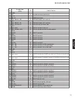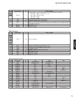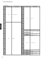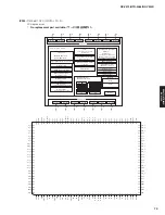
System Switching Pins
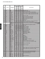
Pin
No.
Function Name
Type
I/O
Detail of Function
76
DSDA0
80
DSDA1
DDC I2C data for respective HDMI receiver port.
84
DSDA2
LVTTL Schmitt Open
drain 5 V tolerant
Input/Output
88
DSDA3
These signals are true open drain, and do not pull to ground when power is not
applied to the device. These pins require an external pull-up resistor.
92
DSDA4
97
DSDA5
DDC I2C data for VGA port.
73
DSDA6(VGA)
LVTTL Schmitt Open
drain 5 V tolerant
Input/Output
This signal is true open drain, and does not pull to ground when power is not
applied to the device. This pin requires an external pull-up resistor.
77
DSCL0
81
DSCL1
DDC I2C clock for respective HDMI receiver port.
85
DSCL2
LVTTL Schmitt Open
drain 5 V tolerant
Input
89
DSCL3
These signals are true open drain, and do not pull to ground when power is not
applied to the device. These pins require an external pull-up resistor.
93
DSCL4
98
DSCL5
DDC I2C clock for VGA port.
74
DSCL6(VGA)
LVTTL Schmitt Open
drain 5 V tolerant
Input
This signal is true open drain, and does not pull to ground when power is not
applied to the device. This pin requires an external pull-up resistor.
DDC master I2C data for HDMI transmitter Port 0.
106
TXDSDA0
LVTTL Schmitt Open
drain 5 V tolerant
Input/Output
This signal is true open drain, and does not pull to ground when power is not
applied to the device. This pin requires an external pull-up resistor.
DDC master I2C data for HDMI transmitter Port 1.
109
TXDSDA1
LVTTL Schmitt Open
drain 5 V tolerant
Input/Output
This signal is true open drain, and does not pull to ground when power is not
applied to the device. This pin requires an external pull-up resistor.
DDC master I2C clock for HDMI transmitter Port 0.
107
TXDSCL0
LVTTL Schmitt Open
drain 5 V tolerant
Input/Output
This signal is true open drain, and does not pull to ground when power is not
applied to the device. This pin requires an external pull-up resistor.
DDC master I2C clock for HDMI transmitter Port 1.
110
TXDSCL1
LVTTL Schmitt Open
drain 5 V tolerant
Input/Output
This signal is true open drain, and does not pull to ground when power is not
applied to the device. This pin requires an external pull-up resistor.
79
R0PWR5V
83
R1PWR5V
5 V port detection input for respective HDMI receiver port.
87
R2PWR5V
Power
Input
Connect to 5 V signal from HDMI input connector. These pins require a 10 ohms
series resistor, a 5.1 k-ohms pull down resistor, and at least a 1 μF capacitor to
ground.
91
R3PWR5V
95
R4PWR5V
100
R5PWR5V
78
CBUS_HPD0
82
CBUS_HPD1
86
CBUS_HPD2
LVTTL 1.5 mA 5 V
tolerant Analog
Input/Output
Hot plug detect output for the respective HDMI receiver port.
90
CBUS_HPD3
In MHL mode, these pins serve as the respective CTRL bus.
94
CBUS_HPD4
99
CBUS_HPD5
105
TX_HPD0
LVTTL 5 V tolerant
Input
Hot plug detect input for HDMI transmitter Port 0.
108
TX_HPD1
LVTTL 5 V tolerant
Input
Hot plug detect input for HDMI transmitter Port 1.
103
MHL_CD0/GPIO0
LVTTL
Input/Output
MHL cable detect 0/programmable GPIO 0.
104
MHL_CD1/GPIO1
LVTTL
Input/Output
MHL cable detect 1/programmable GPIO 1.
65
RX-V475/HTR-4066/RX-V500D
RX-V475/HTR-4066/
RX-V50
0D
Summary of Contents for RX-V500D
Page 9: ...RX V500D A model RX V500D B G models 9 RX V475 HTR 4066 RX V500D RX V475 HTR 4066 RX V500D ...
Page 132: ... CONFIGURING THE SYSTEM SETTINGS RX V475 HTR 4066 RX V500D 133 ...
Page 133: ... システム設定を変更する RX V475 HTR 4066 RX V500D 134 ...
Page 146: ...147 RX V475 HTR 4066 RX V500D RX V475 HTR 4066 RX V500D MEMO ...
Page 147: ...RX V475 HTR 4066 RX V500D ...


