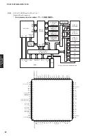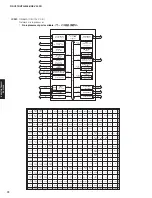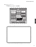
AV-Port 0
AV-Port 2
AV-Port 3
AV-Port 4
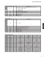
PWM-DAC
UART Interface
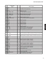
Pin No.
Function Name
I/O
Detail of Function
K4
AOUTLP
O
Left channel PWM output (positive).
L2
AOUTLN
O
Left channel PWM output (negative).
L4
AOUTRP
O
Right channel PWM output (positive).
L3
AOUTRN
O
Right channel PWM output (negative).
Pin No.
Function Name
I/O
Detail of Function
B14
RXD0
I
UART-0 receive signal.
C13
TXD0
O
UART-0 transmit signal.
A14
RXD1
I
UART-1 receive signal.
B13
TXD1
O
UART-1 transmit signal.
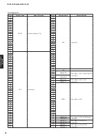
Pin No.
Function Name
I/O
Detail of Function
U3
AV4DATA[1:0]
I/O
Audio data.
V2
Several formats are supported.
Pin No.
Function Name
I/O
Detail of Function
R5
AV3DATA[1:0]
I/O
Audio data.
T4
Several formats are supported.
R4
AV3CLK
I/O
Data clock. Depending on the AV-Port 3 configuration this clock is a bit-clock which is used to transmit or
receive the AV3DATA[
*
] synchronously.
U2
AV3CTRL0
I/O
Configurable sync signal:
Serial audio formats:
LRCK input or output.
T3
AV3CTRL1
I/O
Configurable sync signal:
Serial audio formats:
Master clock output.
Pin No.
Function Name
I/O
Detail of Function
P4
R3
AV2DATA[3:0]
I/O
Audio data.
T2
Several formats are supported.
U1
R1
AV2CLK
I/O
Data clock. Depending on the AV-Port 2 configuration this clock is a bit-clock which is used to transmit or
receive the AV2DATA[
*
] synchronously.
T1
AV2CTRL0
I/O
Configurable sync signal:
Serial audio formats:
LRCK input or output.
R2
AV2CTRL1
I/O
Configurable sync signal:
Serial audio formats:
Master clock output.
Pin No.
Function Name
I/O
Detail of Function
M4
N1
AV0DATA[3:0]
I/O
Audio/video data.
N2
Several formats are supported.
N3
N4
Video data, together with AV0DATA[3:0]:
P1
AV1DATA[3:0]
I/O
AV0DATA[3:0] = video[3:0]
P2
AV1DATA[3:0] = video[7:4]
P3
L1
AV0CLK
I/O
Data clock. Depending on the AV-Port 0 configuration, this clock is a bit- or byte-clock which is used to
transmit or receive the AV0DATA[
*
] synchronously.
Configurable sync signal:
M1
AV0CTRL0
I/O
• Serial audio formats: LRCK input or output.
• Video formats:
PSYNC input or output.
Configurable sync signal:
M2
AV0CTRL1
I/O
• Serial audio formats: Master clock output.
• Video formats:
DVALID input or output.
M3
AV0CTRL2
I/O
Configurable sync signal:
• Video formats:
FSYNC input or output.
73
RX-V475/HTR-4066/RX-V500D
RX-V475/HTR-4066/
RX-V50
0D
Summary of Contents for RX-V500D
Page 9: ...RX V500D A model RX V500D B G models 9 RX V475 HTR 4066 RX V500D RX V475 HTR 4066 RX V500D ...
Page 132: ... CONFIGURING THE SYSTEM SETTINGS RX V475 HTR 4066 RX V500D 133 ...
Page 133: ... システム設定を変更する RX V475 HTR 4066 RX V500D 134 ...
Page 146: ...147 RX V475 HTR 4066 RX V500D RX V475 HTR 4066 RX V500D MEMO ...
Page 147: ...RX V475 HTR 4066 RX V500D ...


