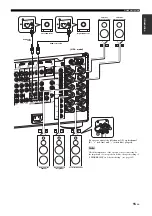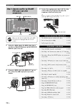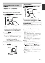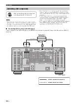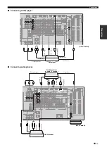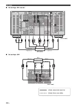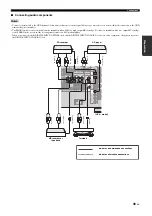
Connections
29
En
Prepara
tion
■
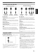
Audio jacks
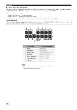
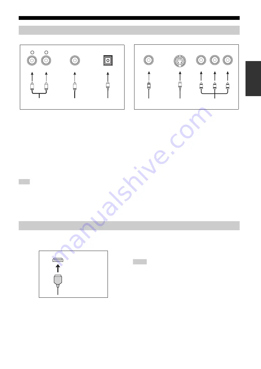
This unit has three types of audio jacks. Connection depends on the
availability of audio jacks on your other components.
AUDIO jacks
For conventional analog audio signals transmitted via left and right
analog audio cables. Connect red plugs to the right jacks and white
plugs to the left jacks.
DIGITAL COAXIAL jacks
For digital audio signals transmitted via coaxial digital audio cables.
DIGITAL OPTICAL jacks
For digital audio signals transmitted via optical digital audio cables.
You can use the digital jacks to input PCM, Dolby Digital and DTS
bitstreams. When you connect components to both the COAXIAL and
OPTICAL jacks, priority is given to the signals input at the COAXIAL jack.
All digital input jacks are compatible with 96-kHz sampling digital signals.
■
Video jacks
This unit has three types of video jacks. Connect the video input
jacks of this unit to the video output jacks of the input source
components to switch the audio and video sources simultaneously.
Connection depends on the availability of input jacks on your video
monitor.
VIDEO jacks
For conventional composite video signals transmitted via composite
video cables.
S VIDEO jacks
For S-video signals, separated into the luminance (Y) and
chrominance (C) video signals transmitted on separate wires of S-
video cables.
COMPONENT VIDEO jacks
For component video signals, separated into the luminance (Y) and
chrominance (P
B
, P
R
) video signals transmitted on separate wires of
component video cables.
y
This unit is equipped with the video conversion function. See pages 30 and
107 for details.
■
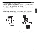
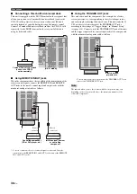
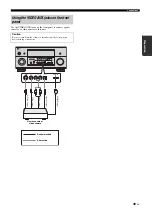
HDMI jack and cable plug
This unit has five HDMI input jacks and two HDMI output jacks for
digital audio and video signal input/output.
y
• We recommend that you use a commercially available HDMI cable shorter
than 5 meters (16 feet) with the HDMI logo printed on it.
• Use a conversion cable (HDMI jack
↔
DVI-D jack) to connect this unit to
other DVI components.
• You can check the potential problem about the HDMI connection (see
• See page 168 for the information on the input signal capability of this unit
for the HDMI connection.
• When you set “Standby Through” in “Manual Setup” to “On”, this unit
allows the HDMI signals input at an HDMI IN jack to pass through this
unit and output at an HDMI OUT jack (see page 113).
• Do not disconnect or connect the cable or turn off the power of the HDMI
components connected to the HDMI OUT jacks of this unit while data is
being transferred. Doing so may disrupt playback or cause noise.
• The HDMI OUT jacks output the audio signals input at the HDMI input
jacks only when “Support Audio” is set to “Other” (see page 113).
• If you turn off the power of the video monitor connected to the HDMI
OUT jacks via a DVI connection, this unit may fail to establish the
connection to the component.
• The analog video signals input at the composite video, S-video and
component video jacks can be digitally up-converted to be output at the
HDMI OUT jacks. Set “Conversion” to “On” in “Manual Setup” (see
page 107) to activate this feature.
• This unit is equipped with two HDMI OUT jacks, however cannot output
the video signals to the both HDMI OUT jacks simultaneously. You can
select the active HDMI OUT jack. See page 54 for details.
Information on jacks and cable plugs
Note
COAXIAL
DIGITAL
AUDIO
OPTICAL
DIGITAL
R
L
C
O
R
L
Left and right analog
audio cable plugs
Optical digital
audio cable plug
Coaxial digital
audio cable plug
Audio jacks and cable plugs
(Red)
(White)
(Orange)
VIDEO
S VIDEO
COMPONENT VIDEO
Y
R
P
B
P
P
B
Y
P
R
S
V
Composite video
cable plug
S-video cable
plug
Component video
cable plugs
Video jacks and cable plugs
(Yellow)
(Green)
(Blue)
(Red)
Information on HDMI™
HDMI
HDMI cable plug
Notes

