20
CONNECTIONS
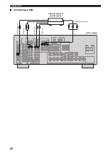
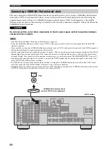
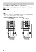
Connect your DVD player, DVD recorder, VCR or STB (set-top box) using the same type of video connections as those
made for your TV (see page 19). The cable TV receiver and the satellite receiver are examples of the STB.
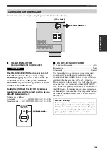
Do not connect this unit or other components to the AC power supply until all connections between
components are complete.
• When “VIDEO CONV.” is set to “OFF” (see page 94), be sure to make the same type of video connections as those made for your TV
(see page 19). For example, if you connected your TV to the VIDEO MONITOR OUT jack of this unit, connect your other
components to the VIDEO jacks.
• When “VIDEO CONV.” is set to “ON” (see page 94), the converted video signals are output only at the MONITOR OUT jacks. When
recording a source, you must make the same type of video connections between each component.
• To make a digital connection to a component other than the default component assigned to each DIGITAL INPUT or DIGITAL
OUTPUT jack, select the corresponding setting for “OPTICAL OUT”, “OPTICAL IN”, or “COAXIAL IN” in “I/O ASSIGNMENT”
(see page 92).
• If you connect your DVD player to both the DIGITAL INPUT (OPTICAL) and the DIGITAL INPUT (COAXIAL) jacks, priority is
given to the signals input at the DIGITAL INPUT (COAXIAL) jack.
■
Connecting a DVD player
Connecting a DVD player, a DVD recorder, a VCR or an STB
Notes
CAUTION
AUDIO
DIGITAL
INPUT
DVD
DVD
COAXIAL
DVD
VIDEO
DVD
COMPONENT VIDEO
P
R
P
B
Y
P
R
P
B
Y
S
V
O
L
R
C
DVD player
Opt
ic
al
au
di
o
o
u
t
Co
axi
al
aud
io
o
u
t
V
ide
o o
u
t
A
u
dio
ou
t
S-
vi
de
o out
Component video out
(U.S.A. model)

